Pressure touch sensitive patient table for tomographic imaging

A patient and medical imaging technology, applied in the field of medical imaging technology, can solve complex problems

Pending Publication Date: 2019-12-06
KONINKLJIJKE PHILIPS NV
View PDF6 Cites 1 Cited by
  • Summary
  • Abstract
  • Description
  • Claims
  • Application Information

AI Technical Summary

Problems solved by technology

However, these devices and techniques require expensive high-resolution and depth-sensing optics and electronics, precise aiming, and complex and computationally intensive processing of the captured video

Method used


Image

  • Pressure touch sensitive patient table for tomographic imaging
  • Pressure touch sensitive patient table for tomographic imaging
  • Pressure touch sensitive patient table for tomographic imaging

Examples


Embodiment Construction

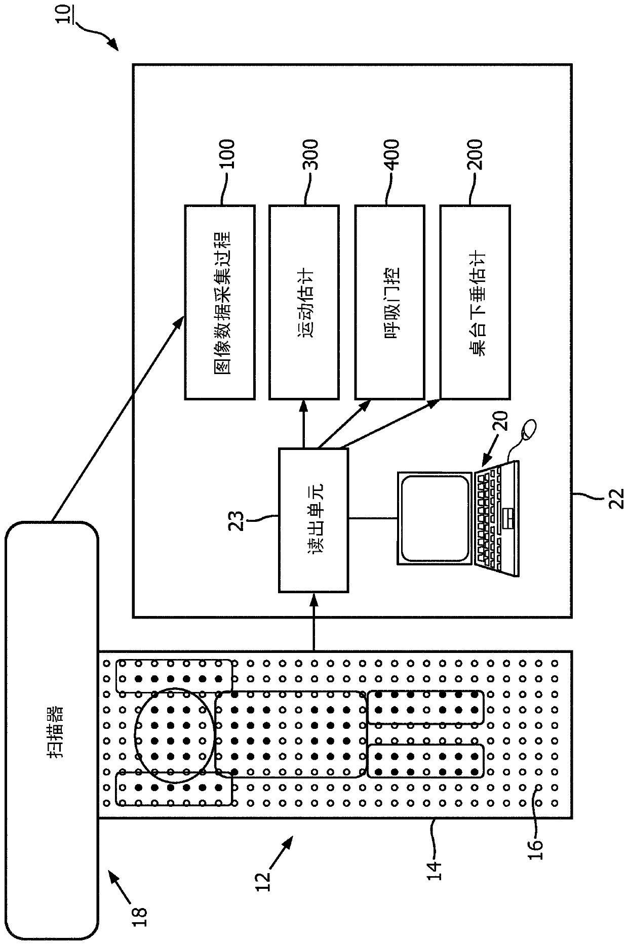
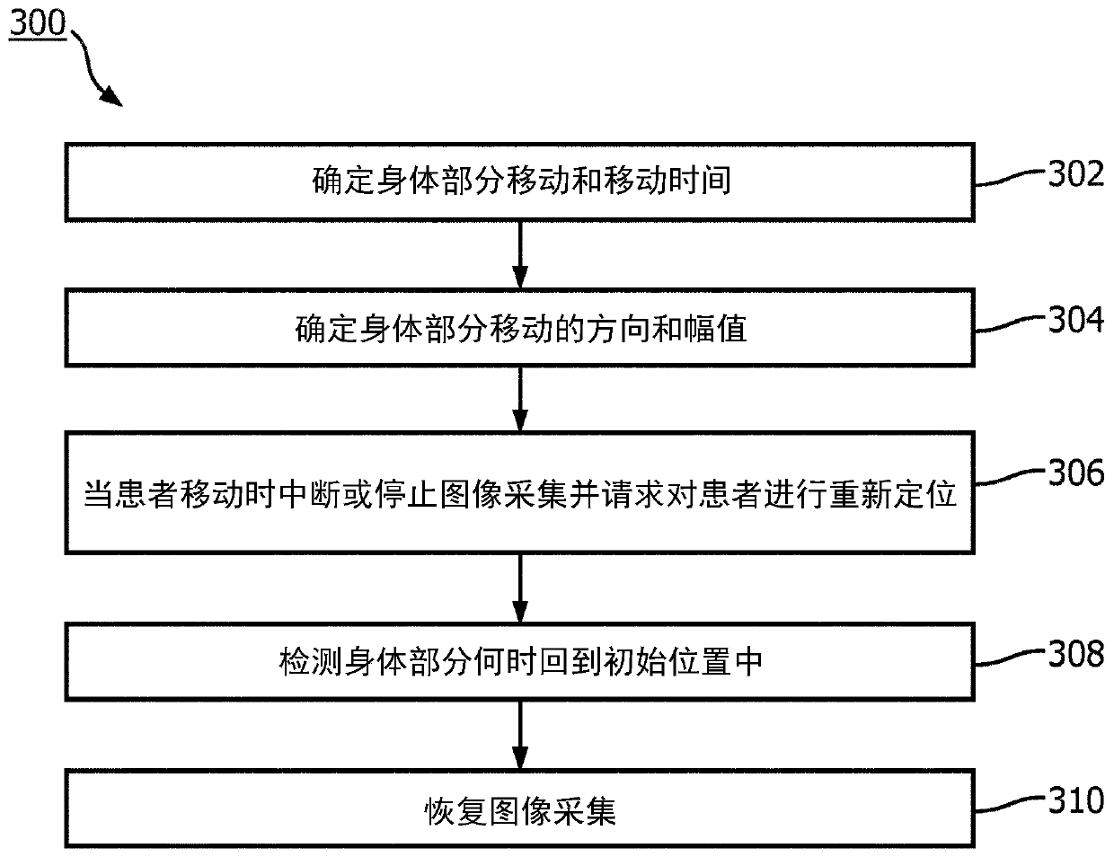
[0018] Various embodiments are disclosed below that utilize an array of pressure sensors disposed on a patient table to address important problems in the field of medical imaging. In some demonstrative embodiments, pressure sensors are used to detect the identity of the body part (eg, leg or arm) moved by the patient, the time of the movement and in some embodiments also the direction of the movement. This information provides guidance on whether to rescan or apply motion correction to parts of the data.

[0019] Respiration information can also be tracked based on pressure readings without any additional equipment being attached to the patient. In some embodiments, a signal of pressure amplitude versus time is measured, from which signal the respiratory period can be estimated. Advantageously, the method is effective even when the chest of a supine patient is lifted from the table during inspiration. As recognized herein, expansion of the chest volume during the breathing c...


PUM


Abstract

A device (10) for a patient to lie on during a medical imaging procedure includes a main body (12). A matrix of pressure sensors (16) disposed on a top surface (14) of the main body are configured tocontinuously measure pressure across the top surface. At least one electronic processor (22) is operatively connected to read the pressure sensors. A non-transitory storage medium stores instructionsreadable and executable by the at least one electronic processor to use the matrix of pressure sensors to perform at least one of: a sag estimation operation (200); a motion estimation operation (300); and a respiratory monitoring operation (400).

Description

technical field [0001] The following generally relates to medical imaging techniques, image localization techniques, image motion correction techniques, and related techniques. Background technique [0002] Real-time motion detection and accurate patient location tracking are areas of great interest in medical imaging and one of the key issues in precision medicine. Some progress has been made by tracking devices using real-time video. However, these devices and techniques require expensive high-resolution and depth-sensing optics and electronics, precise aiming, and complex and computationally intensive processing of the captured video. [0003] Additionally, tracking of breathing patterns allows correction of respiratory motion or respiratory gating during patient scans (eg, computed tomography (CT) scans and positron emission tomography (PET) scans). Simple but reliable detection and tracking of respiratory motion can significantly improve image quality and quantificati...

Claims


Application Information

Patent Timeline
Patent Type & Authority Applications(China)
IPC IPC(8): A61B6/04A61B6/00
CPCA61N2005/1057A61B6/04A61B6/0407A61B6/5276A61B6/541A61B2562/0247A61B2562/046
Inventor A·安德烈耶夫白传勇
Owner KONINKLJIJKE PHILIPS NV
Why Eureka
Try Eureka