
Power converter

Pending Publication Date: 2019-12-06
TOYOTA JIDOSHA KK
View PDF3 Cites 0 Cited by
  • Summary
  • Abstract
  • Description
  • Claims
  • Application Information

AI Technical Summary

Problems solved by technology

Since the current flowing through the power converter is dispersed among multiple power modules connected in parallel, the current capacity of the power converter as a whole increases

Method used


Image

  • Power converter
  • Power converter
  • Power converter

Examples


Embodiment Construction

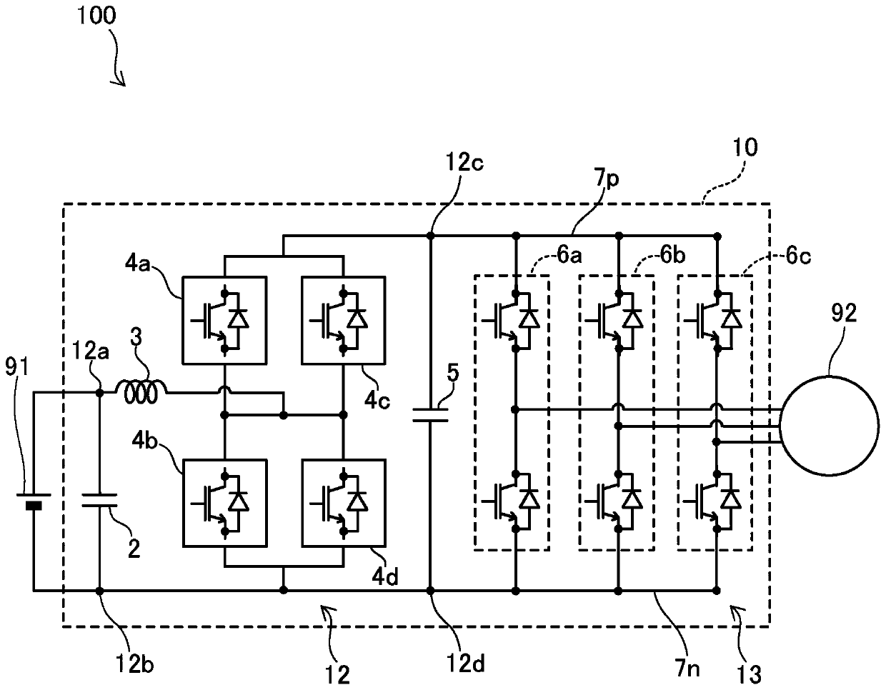
[0044] A power converter according to an embodiment will be described with reference to the drawings. The power converter of the embodiment is mounted on an electric vehicle. figure 1 A block diagram of an electric system of an electric vehicle 100 including the electric power converter 10 is shown. First, the overall circuit configuration of power converter 10 will be described.

[0045] The power converter 10 includes a voltage converter circuit 12 and an inverter circuit 13 . The storage battery 91 is connected to the low-voltage terminals 12a and 12b of the voltage converter circuit 12 (that is, the input terminal of the power converter 10). The DC terminal of the converter circuit 13 is connected to the high voltage terminals 12 c and 12 d of the voltage converter circuit 12 . A capacitor 5 for current smoothing is connected between the voltage converter circuit 12 and the inverter circuit 13 . An electric motor 92 is connected to an AC terminal of the inverter circui...


PUM


Abstract

The invention provides a power converter, which inhibits the resistance difference between current paths of power modules that are parallelly connected. A power module (4a) (PM(4a)) and a power module(4c) (PM(4c)) are parallelly connected by a bus bar. A power module PM(4b) and a power module PM(4d) are parallelly connected by a bus bar. The bus bar may include: a first bus bar piece (31) connecting a negative terminal (4n) of the power module PM(4a) and a positive terminal (4p) of the power module PM(4c); a second bus bar piece (32) connecting a negative terminal of the power module PM(4c) and a positive terminal of the power module PM(4d); and a plurality of connecting bus bar pieces (33-35) connecting the first bus bar piece and the second bus bar piece. PM(4a) and PM(4c) are parallelly connected, and PM(4b) and PM(4d) are also parallelly connected. The connecting bus bar pieces may connect a center of the first bus bar piece and a center of the second bus bar piece.

Description

technical field [0001] The technology disclosed in this specification relates to a power converter including a plurality of power modules housing switching elements. In particular, it relates to a power converter in which at least two power modules are connected in parallel. Background technique [0002] In a power converter using a switching element for power conversion, a power module housing the switching element may be used. Patent Document 1 discloses a power converter using a power module that houses two switching elements. [0003] In order to increase the current capacity of the power converter, a plurality of power modules accommodating switching elements may be connected in parallel. The switching elements of the individual power modules are driven synchronously. Several Power Modules connected in parallel behave like one Power Module. Since the current flowing through the power converter is dispersed among the plurality of power modules connected in parallel, ...

Claims


Application Information

Patent Timeline
IPC IPC(8): H01L25/07H02M7/00
CPCH01L25/072H02M7/003H02M3/158H02M7/5387H02M1/088H02M1/327H02M1/007H02M3/003H05K7/14329H05K7/1432
Inventor 城岛悠树岩田秀一
Owner TOYOTA JIDOSHA KK
Learn More