
Display module and electronic equipment

A technology for display modules and electronic equipment, which is applied in electrical digital data processing, character and pattern recognition, identification devices, etc., can solve problems such as low fingerprint recognition efficiency, and achieve the effect of improving fingerprint recognition efficiency and expanding the area.

Active Publication Date: 2019-12-06
VIVO MOBILE COMM CO LTD
View PDF6 Cites 5 Cited by
  • Summary
  • Abstract
  • Description
  • Claims
  • Application Information

AI Technical Summary

Problems solved by technology

[0005] The invention discloses a display module and electronic equipment to solve the problem of low fingerprint recognition efficiency

Method used


Image

  • Display module and electronic equipment
  • Display module and electronic equipment
  • Display module and electronic equipment

Examples


Embodiment Construction

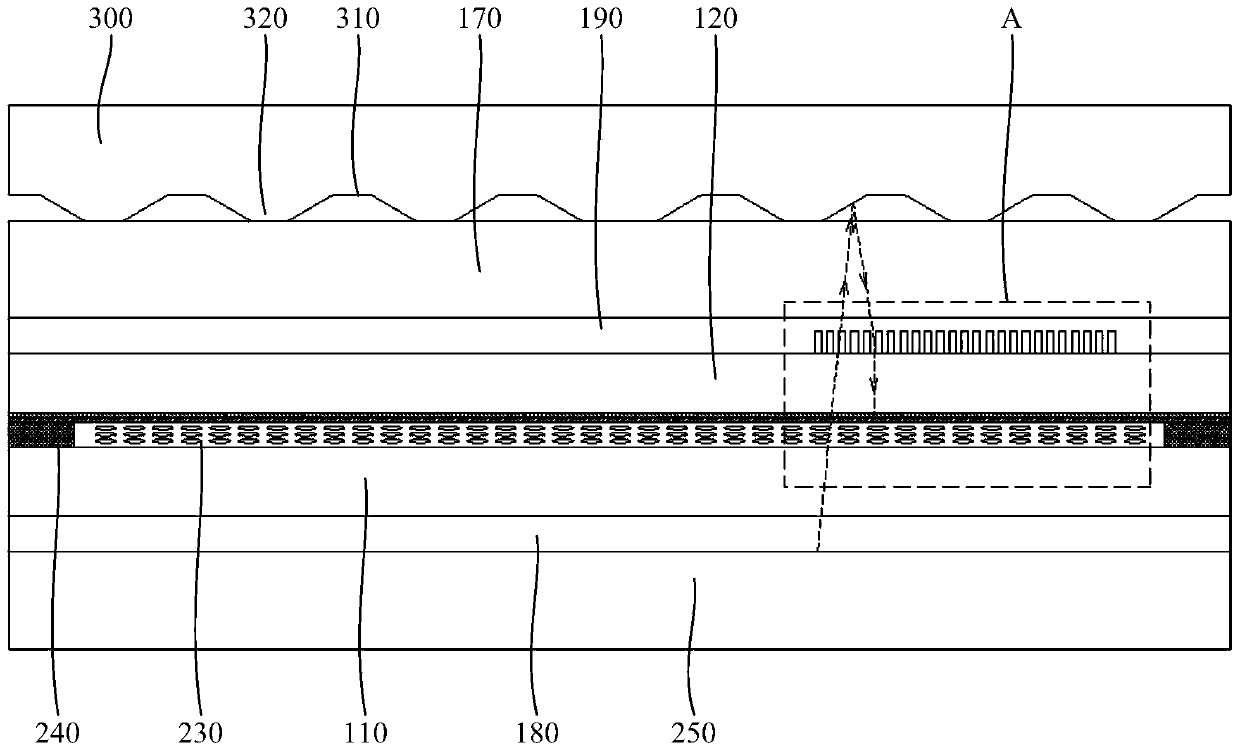
[0017] In order to make the purpose, technical solution and advantages of the present invention clearer, the technical solution of the present invention will be clearly and completely described below in conjunction with specific embodiments of the present invention and corresponding drawings. Apparently, the described embodiments are only some of the embodiments of the present invention, but not all of them. Based on the embodiments of the present invention, all other embodiments obtained by persons of ordinary skill in the art without making creative efforts belong to the protection scope of the present invention.

[0018] The technical solutions disclosed by various embodiments of the present invention will be described in detail below in conjunction with the accompanying drawings.

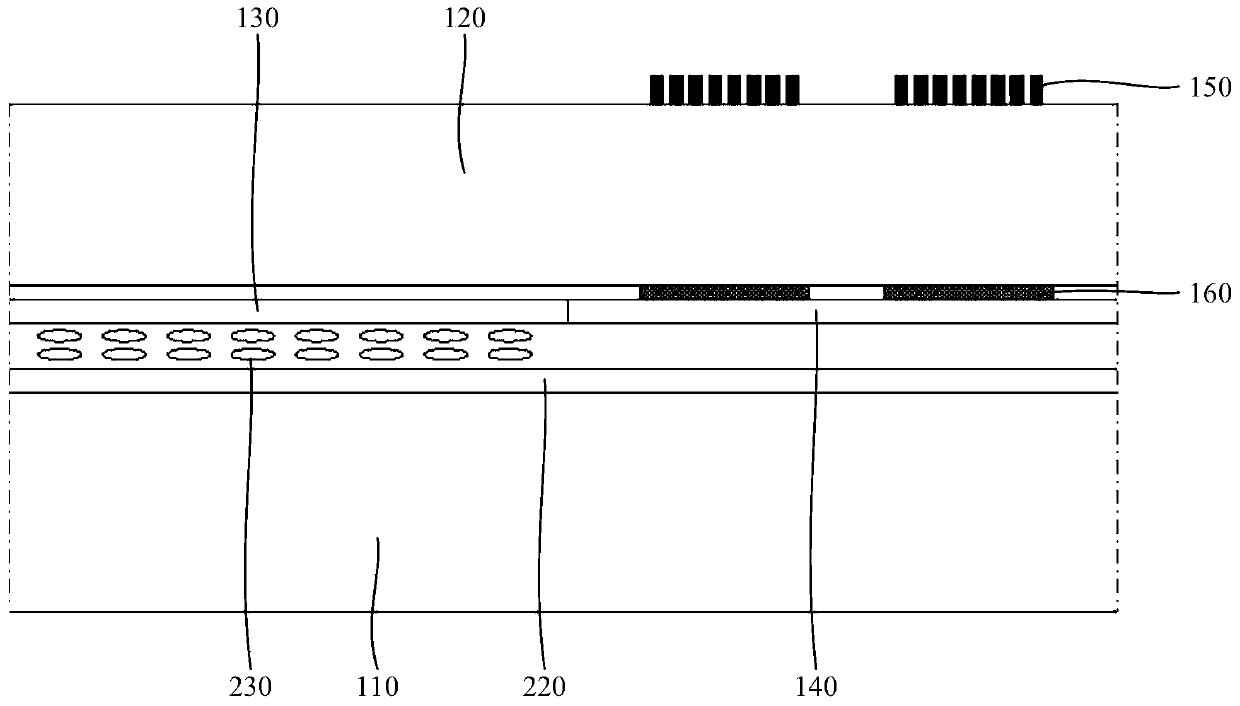
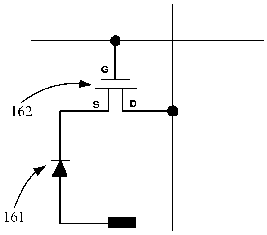
[0019] like figure 1 and figure 2 As shown, the embodiment of the present invention discloses a display module, which can be applied in electronic equipment. The display module may specifica...


PUM


Abstract

The invention discloses a display module and electronic equipment. The display module comprises a first substrate, an image sensor, a color filter layer and a black matrix are arranged on the surfaceof one side of the first substrate, a collimator is arranged on the surface of the other side of the first substrate, the color filter layer and the black matrix are arranged on the same layer, the image sensor is located between the black matrix and the first substrate, and the collimator and the image sensor are arranged at intervals in the direction perpendicular to the first substrate. The image sensor corresponds to the black matrix, and the setting area of the black matrix in the display module is large, so that the collimator and the image sensor can be distributed on the display modulein a large area, the area of a fingerprint identification area on the display module is enlarged, a user can flexibly select the position for placing a finger, and the fingerprint identification efficiency is improved.

Description

technical field [0001] The invention relates to the technical field of display devices, in particular to a display module and electronic equipment. Background technique [0002] The fingerprint module is one of the core components of electronic equipment. With the continuous development of the electronic equipment industry, people have higher and higher requirements for the performance of the fingerprint module, which brings a relatively large challenge to the structural design of the fingerprint module. [0003] The structure of the fingerprint module is various, and the optical fingerprint module that can be arranged under the display screen can improve the appearance and texture of the electronic device, so this kind of fingerprint module has been more and more widely used. The display screen is provided with a fingerprint identification area, and the user can place a finger on the fingerprint identification area, and the fingerprint module below the fingerprint identific...

Claims


Application Information

Patent Timeline
Patent Type & Authority Applications(China)
IPC IPC(8): G06K9/00G06K9/20G09F9/00G02F1/1333
CPCG09F9/00G02F1/13338G06V40/1324G06V40/1318G06V10/145G02F1/13312G06F1/1637G06F1/1684G06F1/1686G02F1/133512G02F1/1368
Inventor 缪国生
Owner VIVO MOBILE COMM CO LTD
Learn More