
Permanent magnet synchronous motor with buffer type rotating speed intelligent speed control structure

A permanent magnet synchronous motor, speed technology, applied in the direction of structural connection, connection with control/drive circuit, electrical components, etc., can solve the problems of poor protection ability, inconvenient speed control, low degree of automation, etc., to achieve convenient adjustment, increase The effect of the big smart control effect

Inactive Publication Date: 2019-12-03
江苏伯海电驱动科技有限公司
View PDF19 Cites 0 Cited by
  • Summary
  • Abstract
  • Description
  • Claims
  • Application Information

AI Technical Summary

Problems solved by technology

[0004] The purpose of the present invention is to provide a permanent magnet synchronous motor with a buffered speed intelligent speed control structure to solve the problems of inconvenient speed control, low degree of automation and poor protection ability in the prior art

Method used

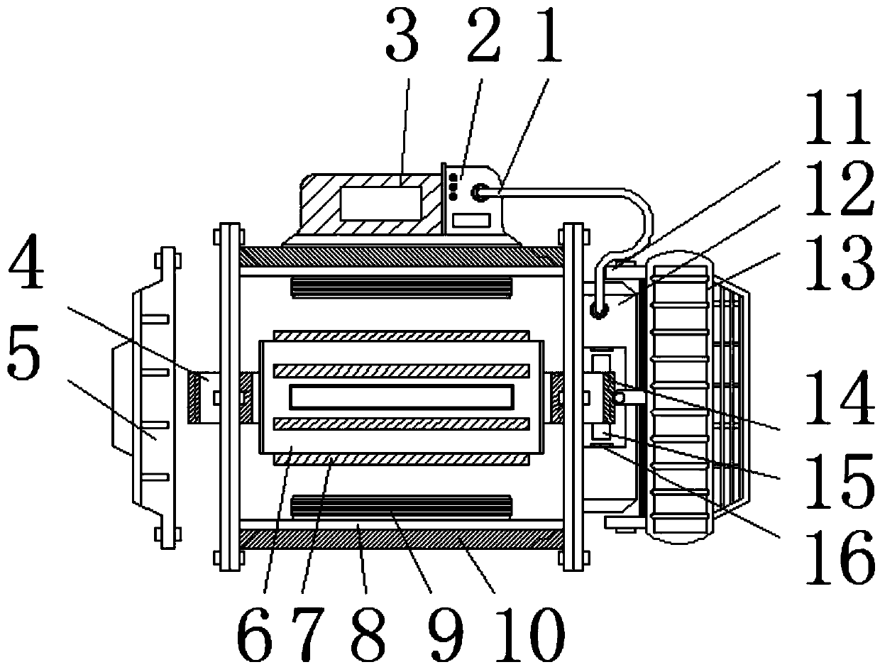
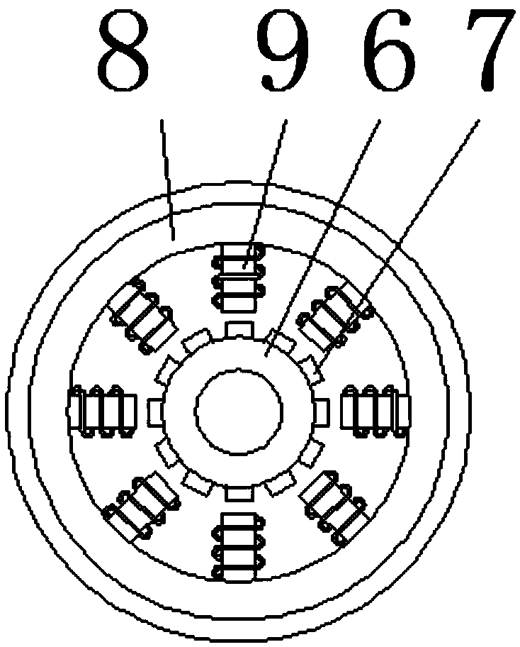
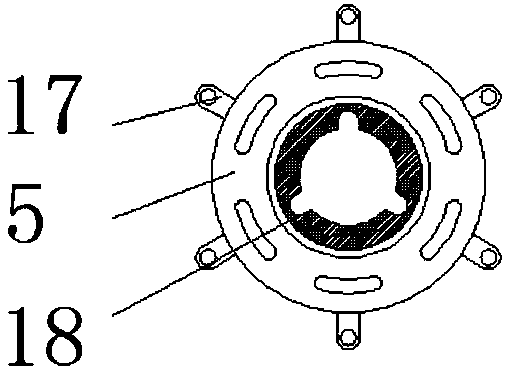

Image

  • Permanent magnet synchronous motor with buffer type rotating speed intelligent speed control structure
  • Permanent magnet synchronous motor with buffer type rotating speed intelligent speed control structure
  • Permanent magnet synchronous motor with buffer type rotating speed intelligent speed control structure

Examples


Embodiment Construction

[0016] The following will clearly and completely describe the technical solutions in the embodiments of the present invention with reference to the accompanying drawings in the embodiments of the present invention. Obviously, the described embodiments are only some, not all, embodiments of the present invention. Based on the embodiments of the present invention, all other embodiments obtained by persons of ordinary skill in the art without making creative efforts belong to the protection scope of the present invention.

[0017] see Figure 1~3 , in an embodiment of the present invention, a permanent magnet synchronous motor with a buffered speed intelligent speed control structure includes a motor housing 10, a stator 8 is installed on the inner side of the motor housing 10, an electromagnetic coil 9 is installed on the inner side of the stator 8, and the motor A driver 3 is installed on the top of the casing 10, a buffer current controller 2 is installed on one side of the dr...


PUM


Abstract

The invention discloses a permanent magnet synchronous motor with a buffer type rotating speed intelligent speed control structure. The permanent magnet synchronous motor comprises a motor shell, a stator is mounted on the inner side of the motor shell, an electromagnetic coil is mounted on the inner side of the stator, a driver is mounted at the top of the motor shell, a butt joint is installed at one end of the second rotating shaft, a first protective cover is installed at one end of the motor shell, an inductive head is installed on the inner side of a rotating speed detector, a second protective cover is installed on the outer side of the rotating speed detector, and a cable is installed between the rotating speed detector and a buffer flow controller. The rotating speed detector is installed at one end of the motor shell, the inductive head is installed on the inner side of the rotating speed detector, a second rotating shaft is installed at one end of the rotor, the butt joint is installed on the second rotating shaft, the butt joint is located in the rotating speed detector, and the butt joint and the inductive head interact with each other.

Description

technical field [0001] The invention relates to the field of permanent magnet synchronous motors, in particular to a permanent magnet synchronous motor with a buffered speed intelligent speed control structure. Background technique [0002] The components of permanent magnet synchronous motor: stator, permanent magnet steel rotor, position sensor, electronic reversing switch, etc. The permanent magnet synchronous motor has the advantages of simple structure, small size, light weight, low loss, high efficiency, high power factor, etc. It is mainly used for the update of high-performance servo drive systems and DC motors that require fast response, wide speed range, and accurate positioning. Replacement motor. The so-called permanent magnet synchronous motor is a sine wave permanent magnet synchronous motor. Like a general synchronous motor, the stator winding of a sine wave PMSM usually adopts a three-phase symmetrical sinusoidal distribution winding, or the rotor uses a spe...

Claims


Application Information

Patent Timeline
Patent Type & Authority Applications(China)
IPC IPC(8): H02K11/21H02K11/30
CPCH02K11/21H02K11/30
Inventor 李红江吴春扣苏吉刚蔡忠伟
Owner 江苏伯海电驱动科技有限公司
Learn More