A steel flatness detection system

A detection system and flatness technology, which is applied in the general control system, control/regulation system, measuring device, etc., can solve the problem of being unable to detect the flatness of both sides of steel at the same time, unable to realize assembly line detection, and unable to distinguish superior and inferior products, etc. problem, to achieve the effect of saving manpower handling, simple structure and fast detection

Active Publication Date: 2020-11-24
萧县众科电磁检测有限公司
View PDF7 Cites 0 Cited by
  • Summary
  • Abstract
  • Description
  • Claims
  • Application Information

AI Technical Summary

Problems solved by technology

[0003] The existing steel flatness detection system has certain disadvantages in use. First, the traditional steel flatness detection system cannot realize assembly line detection, and can only detect a single piece. It is time-consuming and labor-intensive to detect a large number of steel products. Secondly, the existing steel The flatness detector cannot detect the flatness of both sides of the steel at the same time. It is necessary to manually turn the steel over and re-test, which is time-consuming and labor-intensive. It threatens the safety of workers and affects the accuracy of detection. Finally, the existing steel flatness detection system is only It can detect, but cannot distinguish between good and bad products, and it is necessary to manually watch the test results to remove the defective products. In view of the shortcomings of the existing technology, we propose a steel flatness detection system

Method used


Image

  • A steel flatness detection system
  • A steel flatness detection system
  • A steel flatness detection system

Examples


Embodiment Construction

[0026] In order to make the technical means, creative features, goals and effects achieved by the present invention easy to understand, the present invention will be further described below in conjunction with specific embodiments.

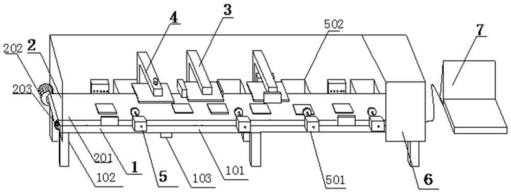
[0027] Such as Figure 1-5 As shown, a steel flatness detection system includes an operation platform 1, the upper surface of the operation platform 1 is provided with a transmission mechanism 2, and the upper surface of the operation platform 1 is fixedly connected with a detection mechanism 3 on both sides of the transmission mechanism 2, and the operation A rotating mechanism 4 is fixedly connected to the back side of the upper surface of the table 1 , waste recycling mechanisms 5 are fixedly connected to both sides of the operation table 1 , and a system casing 6 is sleeved outside the operation table 1 .

[0028] Further, the console 1 includes a desktop 101, the middle and four corners of the lower surface of the desktop 101 are fixedly conn...


PUM


Abstract

The invention discloses a steel flatness detection system. The system comprises an operating table, a conveying mechanism is arranged on an upper surface of the operation table, detection mechanisms are fixedly connected to the upper surface of the operation table on two sides of the conveying mechanism, a rotating mechanism is fixedly connected to a back side of the upper surface of the operationtable, waste recycling mechanisms are fixedly connected to two sides of the operation table in an extending mode, and the operation table is sleeved with a system shell. The invention relates to thesteel flatness detection system, by setting a conveying belt is driven by a motor, a magnet is attracted by a steel to automatically trigger an optical transmitter to transmit a light beam, the full-flow unmanned detection can be realized, the intelligent level is high, the detection is rapid, the system only turns on the optical transmitter only when a steel to be detected arrives through the magnet, a contact electrode and a fixed electrode, the optical transmitter is automatically turned off after the detection is completed, the automation level is high, electric energy is saved, and the economical efficiency is high.

Description

technical field [0001] The invention relates to the field of steel material detection, in particular to a steel material flatness detection system. Background technique [0002] Steel is a material of a certain shape, size and performance made of steel ingots, billets or steel through pressure processing. Most steel processing is through pressure processing to cause plastic deformation of the processed steel (billet, ingot, etc.), and the steel is processed at the factory. Finally, it is necessary to detect the smoothness of its surface to detect its qualified quality, which requires a steel flatness detection system. [0003] The existing steel flatness detection system has certain disadvantages in use. First, the traditional steel flatness detection system cannot realize assembly line detection, and can only detect a single piece. It is time-consuming and labor-intensive to detect a large number of steel products. Secondly, the existing steel The flatness detector cannot ...

Claims


Application Information

Patent Timeline
Patent Type & Authority Patents(China)
IPC IPC(8): G01B11/30G05B15/02
CPCG01B11/306G05B15/02
Inventor 周伟伟
Owner 萧县众科电磁检测有限公司
Why Eureka
Try Eureka