
Solid waste treatment device

A solid waste and processing equipment technology, applied in grain processing, lighting and heating equipment, combustion methods, etc., can solve problems that endanger health and normal life and production, affect sustainable economic development, and inconvenience solid waste crushing, etc. Achieve the effects of reducing the generation of nitrogen oxides and sulfur oxides, good crushing effect, and reducing the amount of treatment

Inactive Publication Date: 2019-12-03
徐飞
View PDF5 Cites 4 Cited by
  • Summary
  • Abstract
  • Description
  • Claims
  • Application Information

AI Technical Summary

Problems solved by technology

[0002] Solid waste refers to solid and semi-solid waste produced by humans in production, consumption, life and other activities (the definition abroad is more extensive, and waste produced by animal activities also falls into this category). In layman's terms, it is " Garbage", with the development of urbanization, there are more and more solid wastes. Solid wastes have directly endangered people's health, normal life and production, and affected the sustainable development of the economy. The existing solid waste treatment equipment is not well installed. However, it is not convenient to completely crush solid wastes of different sizes, which is not conducive to further treatment in the later stage. At present, the main treatment method of solid waste is incineration. However, during the incineration process, a large number of the most toxic and extremely toxic Strong carcinogenic polluting gases are produced, and once these pollutants are discharged beyond the standard, they will have a bad impact on the environment

Method used


Image

  • Solid waste treatment device
  • Solid waste treatment device
  • Solid waste treatment device

Examples


Embodiment Construction

[0023] The following will clearly and completely describe the technical solutions in the embodiments of the present invention with reference to the accompanying drawings in the embodiments of the present invention. Obviously, the described embodiments are only some, not all, embodiments of the present invention. Based on the embodiments of the present invention, all other embodiments obtained by persons of ordinary skill in the art without making creative efforts belong to the protection scope of the present invention.

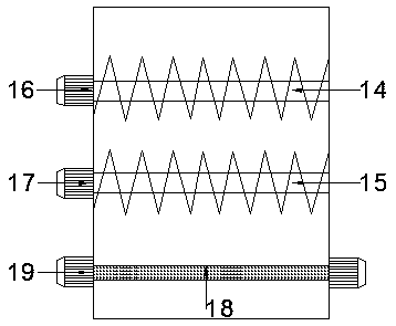
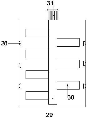
[0024] see Figure 1-5 , the present invention provides a technical solution: a solid waste treatment equipment, including a workbench 1, the bottom of the workbench 1 is provided with a support foot 2, and the support foot 2 and the workbench 1 are fixedly welded , the top of the workbench 1 is sequentially provided with a crushing box 3, a control box 4, a decomposition chamber 5, a combustion chamber 6 and a treatment chamber 7, the crushing box 3 is arrang...


PUM


Abstract

The invention discloses a solid waste treatment device. The device comprises a workbench, the supporting legs are arranged under the workbench and are fixedly welded with the workbench, and a crushingbox, a control box, a decomposition chamber, a combustion chamber and a treatment chamber are sequentially arranged above the workbench. The crushing box is arranged above the control box, a discharging pipe is arranged at the bottom of the crushing box, and a first conveying pipe is arranged at the bottom of the discharging pipe. The smashing box, the discharging pipe and the first conveying pipe are fixedly connected in sequence, the material conveying pipe I is arranged above the control box, and the decomposition chamber is arranged at one side of the control box; the decomposition chamber is connected with the material conveying pipe I, the combustion chamber is arranged at the side, away from the control box, of the decomposition chamber and is connected with the decomposition chamber through a material conveying pipe II, the treatment chamber is arranged at the side, away from the decomposition chamber, of the combustion chamber and is connected with the combustion chamber through an air outlet pipeline, and an air extracting pump is installed at one side of the air outlet pipeline. The solid waste treatment device enables the waste to be burnt fully, and is better in treatment effect.

Description

technical field [0001] The invention relates to the technical field of environmental protection equipment, in particular to solid waste treatment equipment. Background technique [0002] Solid waste refers to solid and semi-solid waste produced by humans in production, consumption, life and other activities (the definition abroad is more extensive, and waste produced by animal activities also falls into this category). In layman's terms, it is " Garbage", with the development of urbanization, there are more and more solid wastes, which have directly endangered people's health, normal life and production, and affected the sustainable development of the economy. The existing solid waste treatment equipment is not well installed However, it is not convenient to completely crush solid wastes of different sizes, which is not conducive to further treatment in the later stage. At present, the main treatment method of solid waste is incineration. However, during the incineration pro...

Claims


Application Information

Patent Timeline
Patent Type & Authority Applications(China)
IPC IPC(8): F23G5/033F23G5/027F23G5/30F23G5/44F23J15/04F23J15/06B02C21/00B02C23/16
CPCB02C21/00B02C23/16B02C2023/165B02C2201/06F23G5/0276F23G5/033F23G5/30F23G5/44F23G2201/304F23G2201/80F23J15/022F23J15/04F23J15/06F23J2217/50
Inventor 徐飞
Owner 徐飞
Learn More