Cross beam for viaduct type gantry machining center

A technology for viaducts and beams, used in metal processing equipment, metal processing machinery parts, manufacturing tools, etc., can solve the problems of insufficient beam rigidity, increased torsional deformation of beams, and large overturning moment, so as to facilitate on-site management and reduce overturning moment. , the effect of improving the versatility

Pending Publication Date: 2019-12-03
NINGBO HAITIAN PRECISION MASCH CO LTD
View PDF0 Cites 0 Cited by
  • Summary
  • Abstract
  • Description
  • Claims
  • Application Information

AI Technical Summary

Problems solved by technology

Because the beam is not a regular front-to-back symmetrical structure, the center of gravity is biased towards the front side of the beam, and the mass of the ram part is relatively large, so the overturning moment of the ram part (that is, the roll moment of the forward roll) is relatively large, which makes the torsion of the beam Increased deformation, resulting in insufficient beam rigidity

Method used


Image

  • Cross beam for viaduct type gantry machining center
  • Cross beam for viaduct type gantry machining center
  • Cross beam for viaduct type gantry machining center

Examples


Embodiment 1

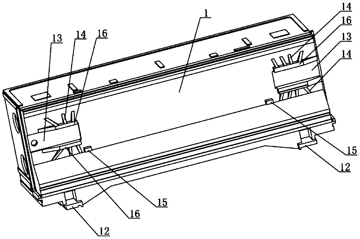
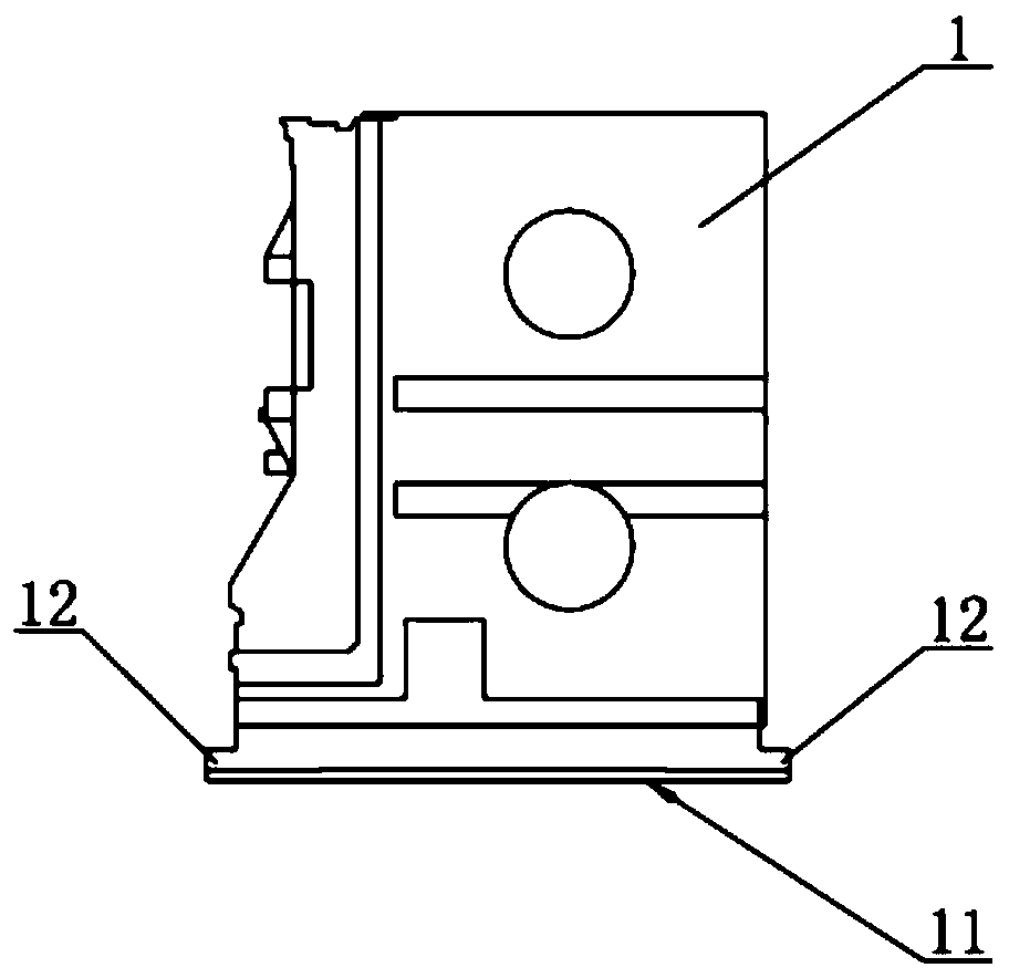
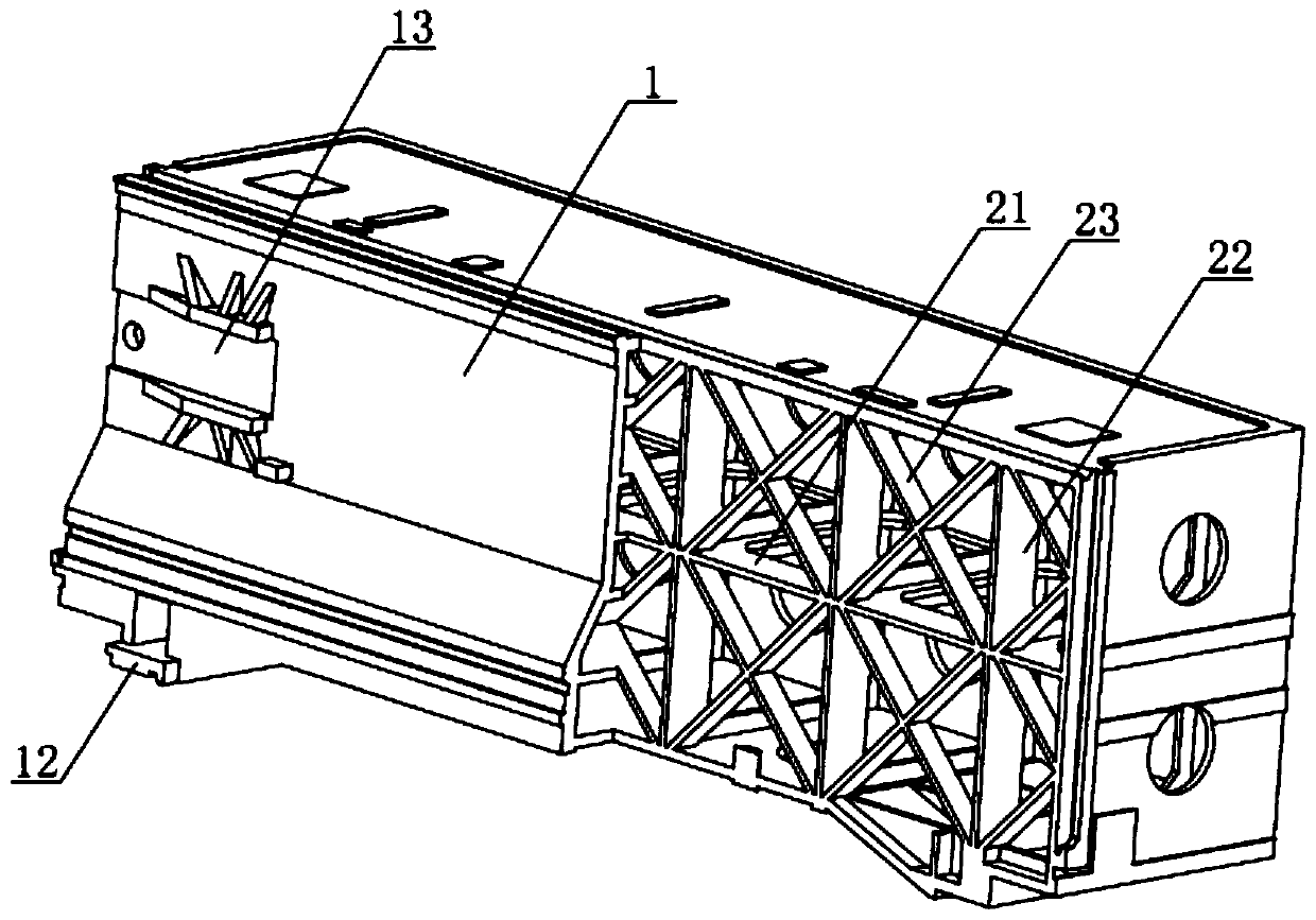
[0030] The beam used for the viaduct-type gantry machining center of Example 1, as shown in the figure, includes a beam body 1, which is a box structure, and the inner cavity of the beam body 1 is integrally connected with a reinforcement mesh, and the reinforcement mesh It is composed of staggered ribbed plates; the bottom surface of the beam body 1 is provided with two slider mounting surfaces 11, the beam body 1 is a left-right symmetrical structure, and the two slider mounting surfaces 11 are symmetrically arranged left and right, and the front side of the bottom of the beam body 1 and the rear side are provided with two protruding bosses 12, the front side and the rear side of each slider mounting surface 11 correspond to a boss 12 respectively, and the bottom surface of each boss 12 is flush with a slider mounting surface 11 flat.

[0031] In Embodiment 1, a first positioning groove 17 and a second positioning groove 18 are respectively opened on the left and right sides...

Embodiment 2

[0033] The difference between the beam used for the viaduct-type gantry machining center of Embodiment 2 and Embodiment 1 is that in Embodiment 2, two screw mounting parts 13 are provided on the front side of the beam body 1, and the two screw mounting parts 13 The left and right are arranged symmetrically, and the outer side of each screw mounting part 13 is provided with a plurality of triangular ribs 14 distributed radially at intervals centered on the screw mounting part 13, and the plurality of triangular ribs 14 are integrally connected with the beam body 1; Two limit blocks 15 are connected to the front side of the beam body 1 , and the two limit blocks 15 are located between the two lead screw mounting parts 13 .

[0034] In Embodiment 2, a trapezoidal rib 16 arranged horizontally is connected to the upper side and the lower side of each screw mounting part 13, and each trapezoidal rib 16 is connected with a plurality of triangular ribs 14 distributed radially at interv...


PUM


Abstract

The invention discloses a cross beam for a viaduct type gantry machining center. The cross beam includes a cross beam body, wherein two sliding block mounting surfaces are arranged on the bottom surface of the cross beam body; the cross beam body is of a bilateral symmetry structure; the two sliding block mounting surfaces are arranged in a bilateral symmetry mode; the front side and the rear sideof the bottom of the cross beam body are respectively provided with two outwards-extending bosses; the front side and the rear side of each sliding block mounting surface correspond to one boss respectively; and the bottom face of each boss is flush with one sliding block mounting surface. The cross beam adopts a modular design, so that the follow-up performance of the cross beam body structure can be improved, and the influence of a heat source on a machine tool is minimized; the cross beam is good in rigidity, low in cost, good in universality, convenient to assemble, capable of effectivelyreducing the overturning moment of the ram part, reducing the torsional deformation of the cross beam body, improving the rigidity of the cross beam and guaranteeing the precision of a machine tool,and capable of being universally applied to viaduct type gantry machining centers applied to different fields such as aerospace, the mold industry and the traditional manufacturing industry.

Description

technical field [0001] The invention relates to a beam of a machining center, in particular to a beam used for a viaduct type gantry machining center. Background technique [0002] In recent years, high-speed cutting has been widely used in my country's mold and tool manufacturing and the processing of complex curved surfaces and thin-walled parts in the aerospace field. With the subdivision of the industry, the machine tool industry needs to continuously introduce products for different industries. For the viaduct-type gantry machining center, in the aerospace field, the machine tool is required to be equipped with a five-axis head, and the requirements for feed, rapid traverse speed and spindle speed are very high; the mold industry requires a five-axis head or a 3+2 swing head. In the field of aerospace, the requirements for feed and speed are not particularly high, but the requirements for the precision and surface quality of the mold are very high; in the traditional m...

Claims


Application Information

Patent Timeline
Patent Type & Authority Applications(China)
IPC IPC(8): B23Q1/01
CPCB23Q1/01B23Q1/012B23Q1/015
Inventor 邬伟军蒋思宝廖敏高玉琢孟浩权周浩东
Owner NINGBO HAITIAN PRECISION MASCH CO LTD
Why Eureka
Try Eureka