
Frequency spectrum detection system

A technology of spectrum and frequency-sweeping light source, which is applied in the field of spectrum detection system, can solve the problems of large frequency measurement error, limited frequency resolution, optical time gate accuracy, and inability to meet the application requirements of electronic warfare systems, and achieve narrow spectrum detection , The effect of broadband spectrum detection

Active Publication Date: 2019-11-29
INST OF SEMICONDUCTORS - CHINESE ACAD OF SCI
View PDF6 Cites 7 Cited by
  • Summary
  • Abstract
  • Description
  • Claims
  • Application Information

AI Technical Summary

Problems solved by technology

Frequency measurement based on photonics channelization technology can achieve large bandwidth, but its frequency measurement error is very large, usually greater than 1GHz, which cannot meet the application requirements of most electronic warfare systems; the method based on frequency-to-power mapping can achieve relatively more High-precision frequency detection, but this method can only detect single-frequency microwave signals, and cannot simultaneously detect multiple point-frequency signals, so its application is limited
The method based on frequency-to-time mapping can realize the detection of multi-point frequency signals, but at the same time, the frequency resolution of this method is limited by the accuracy of the optical time gate in the system, which is on the order of hundreds of MHz

Method used


Image

  • Frequency spectrum detection system
  • Frequency spectrum detection system
  • Frequency spectrum detection system

Examples


Embodiment Construction

[0034] In order to make the object, technical solution and advantages of the present invention clearer, the present invention will be further described in detail below in conjunction with specific embodiments and with reference to the accompanying drawings.

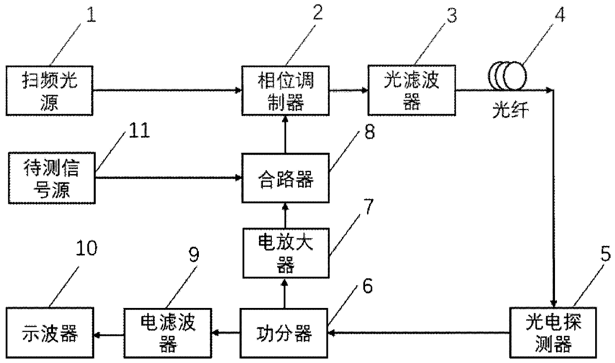
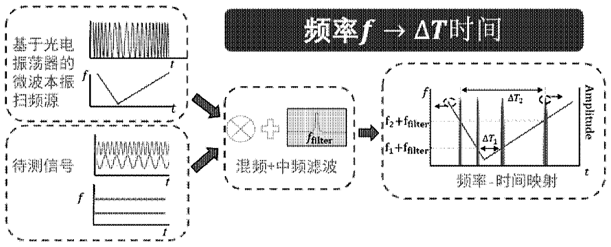
[0035] The present invention is based on microwave photon technology, couples the signal to be measured to a Fourier domain mode-locked photoelectric oscillator, uses a suitable electric filter to filter and uses the corresponding relationship between the output frequency and time of the Fourier domain mode-locked photoelectric oscillator , that is to use the frequency-sweeping characteristic of the Fourier-domain mode-locked optoelectronic oscillator to realize the mapping from the frequency of the injected microwave signal to the time, so as to realize the high-precision detection of the unknown microwave signal. Furthermore, the present invention also utilizes the frequency-sweeping microwave generation performance of t...


PUM


Abstract

A frequency spectrum detection system comprises a swept source, a phase modulator, an optical filter, a photoelectric detector, a power divider, an electric amplifier, a combiner, an electric filter and an oscilloscope. The swept source, the phase modulator, the optical filter, the photoelectric detector and the electric amplifier form an annular photoelectric oscillator resonant cavity. When a Fourier domain mode locking condition is satisfied, a resonant cavity of the photoelectric oscillator can generate a swept-frequency signal with an adjustable broadband. A to-be-measured signal is coupled to a Fourier domain mode-locked photoelectric oscillator, the to-be-measured signal is subjected to oscillation signal beat frequency in a loop and the photoelectric oscillator, and the time domainwaveform of the output signal is observed through an oscilloscope after the to-be-measured signal is filtered by an electric filter. Mapping from frequency to time of a to-be-measured signal is realized by using a Fourier domain mode-locked photoelectric oscillator, and frequency information of the to-be-measured signal can be obtained through appearance time of a waveform observed by an oscilloscope.

Description

technical field [0001] The invention relates to the technical field of microwave photonics, in particular to a spectrum detection system. Background technique [0002] In radar and other electronic warfare systems, the ability to accurately measure intercepted unknown microwave signals is critical. Modern electronic technology can achieve high-precision frequency detection, but the frequency of the signal to be tested may be distributed in a wide frequency band, and the frequency bandwidth is limited when using purely electronic methods, and the measurement is susceptible to electromagnetic interference . [0003] The above-mentioned disadvantages of electronic technology can be avoided by adopting the method of photonics. In principle, photonics-based microwave signal frequency detection schemes can be roughly divided into three categories, namely, based on photonics channelization technology, based on frequency-to-power mapping, and based on frequency-to-time mapping. F...

Claims


Application Information

Patent Timeline
Patent Type & Authority Applications(China)
IPC IPC(8): H04B10/079H04B10/548H04B17/00
CPCH04B10/079H04B17/00H04B10/548G01R23/17G01R23/163G01R23/165
Inventor 李明郝腾飞唐健石暖暖李伟祝宁华
Owner INST OF SEMICONDUCTORS - CHINESE ACAD OF SCI
Learn More