
Display panel driving method, driving device and display device

A technology of display panel and driving method, which is applied to static indicators, instruments, etc., can solve the problems of insufficient scanning time, dark display image, mixed noise of analog signal, etc., so as to increase scanning time, improve resolution, and improve display image. darker effect

Active Publication Date: 2021-06-18
CHENGDU VISTAR OPTEOLECTRONICS CO LTD
View PDF8 Cites 0 Cited by
  • Summary
  • Abstract
  • Description
  • Claims
  • Application Information

AI Technical Summary

Problems solved by technology

[0002] At present, the light-emitting system mainly includes two driving modes, analog drive and digital drive, in terms of gray scale realization. To adjust the luminance of light-emitting devices, analog signals are easily mixed with noise, and it is difficult to achieve high-precision control of the display gray scale of light-emitting devices. Digital drive circuits are more and more widely used due to their low image noise and fast switching speed.
[0003] With the improvement of frame rate and display grayscale requirements, the traditional scanning algorithm is no longer applicable, and the concept of sub-field has been applied to various digital drive algorithms. The scanning time of the currently used sub-field scanning algorithm is insufficient, and further Insufficient data storage leads to dark display images

Method used


Image

  • Display panel driving method, driving device and display device
  • Display panel driving method, driving device and display device
  • Display panel driving method, driving device and display device

Examples


Embodiment Construction

[0051] The present invention will be further described in detail below in conjunction with the accompanying drawings and embodiments. It should be understood that the specific embodiments described here are only used to explain the present invention, but not to limit the present invention. In addition, it should be noted that, for the convenience of description, only some structures related to the present invention are shown in the drawings but not all structures.

[0052] Just like the background technology, with the improvement of frame rate and display grayscale requirements, the traditional scanning algorithm is no longer applicable, and the concept of sub-field has been applied to various digital driving algorithms. The scanning algorithm of sub-field scanning currently used Insufficient time leads to insufficient data storage and dark display images. The specific analysis is as follows:

[0053] The scanning time in the current sub-field scanning algorithm is inversely ...


PUM


Abstract

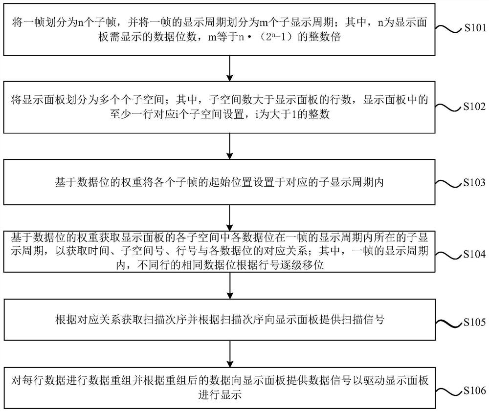
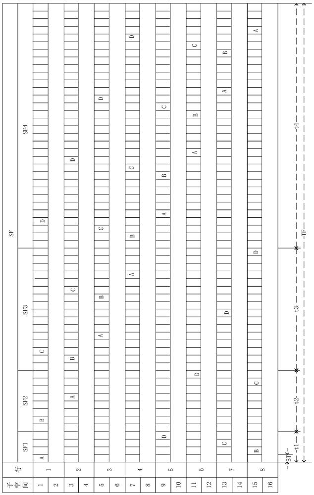
The embodiment of the present invention discloses a driving method of a display panel, a driving device thereof, and a display device. The driving method of the display panel includes dividing a frame into n subframes, and dividing a display period of a frame into m subdisplay periods; Divide the display panel into a plurality of subspaces; the number of subspaces is greater than the number of rows of the display panel; based on the weight of the data bits, the sub-display period where each data bit in each subspace of the display panel is located within the display period of one frame is obtained, so as to Obtain the corresponding relationship between time, subspace number, line number and each data bit; obtain the scanning order according to the corresponding relationship and provide scanning signals to the display panel according to the scanning order; perform data reorganization on each row of data and send data to the display panel according to the reorganized data Provide data signals to drive the display panel for display. Through the technical scheme of the present invention, while realizing the data driving of the display panel, the scanning time of each data bit is increased.

Description

technical field [0001] Embodiments of the present invention relate to the field of display, and in particular to a method for driving a display panel, a driving device thereof, and a display device. Background technique [0002] At present, the light-emitting system mainly includes two driving modes, analog drive and digital drive, in terms of gray scale realization. To adjust the luminance of light-emitting devices, analog signals are easily mixed with noise, and it is difficult to achieve high-precision control of the display gray scale of light-emitting devices. However, digital driving circuits are more and more widely used because of their low image noise and fast switching speed. [0003] With the improvement of frame rate and display grayscale requirements, the traditional scanning algorithm is no longer applicable, and the concept of sub-field has been applied to various digital drive algorithms. The scanning time of the currently used sub-field scanning algorithm is...

Claims


Application Information

Patent Timeline
Patent Type & Authority Patents(China)
IPC IPC(8): G09G3/32G09G3/3208G09G3/3266G09G3/3275
CPCG09G3/32G09G3/3208G09G3/3266G09G3/3275
Inventor 张东豪
Owner CHENGDU VISTAR OPTEOLECTRONICS CO LTD
Learn More