Assembled multilayer optical fiber distribution frame

An optical fiber distribution frame and multi-layer technology, which is applied in the field of assembling multi-layer optical fiber distribution frames, can solve the problems of dust collection, increase the risk of use, and reduce the overall appearance, so as to improve the use firmness and practicability. and economical

Inactive Publication Date: 2019-11-29
合肥昌嵩精密制造有限公司
View PDF6 Cites 0 Cited by
  • Summary
  • Abstract
  • Description
  • Claims
  • Application Information

AI Technical Summary

Problems solved by technology

[0004] The purpose of the present invention is to provide an assembled multi-layer optical fiber distribution frame to solve the problem that the two-way insertion slots of the optical fiber distribution frame proposed in the above background technology are not covered, that is, the optical fiber bus is connected to the slot from the slot. When entering the body, there is no corresponding sealing device to seal the notch, which will easily cause a large amount of dust and particles in the external environment to enter the body from the notch to cause dust collection. On the one hand, the overall appearance of the body will be greatly reduced. On the other hand, the long-term accumulation of dust in the past will increase the danger of use during use, and there is a large potential safety hazard

Method used


Image

  • Assembled multilayer optical fiber distribution frame
  • Assembled multilayer optical fiber distribution frame
  • Assembled multilayer optical fiber distribution frame

Examples


Embodiment Construction

[0023] The following will clearly and completely describe the technical solutions in the embodiments of the present invention with reference to the accompanying drawings in the embodiments of the present invention. Obviously, the described embodiments are only some, not all, embodiments of the present invention. Based on the embodiments of the present invention, all other embodiments obtained by persons of ordinary skill in the art without making creative efforts belong to the protection scope of the present invention.

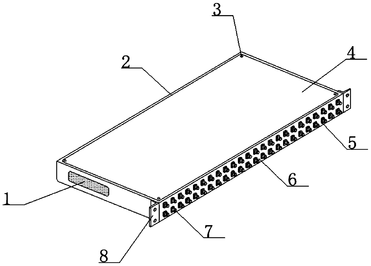
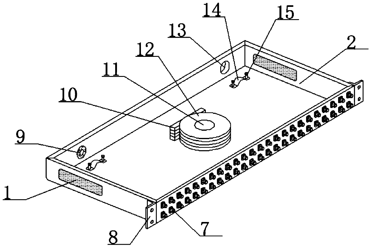
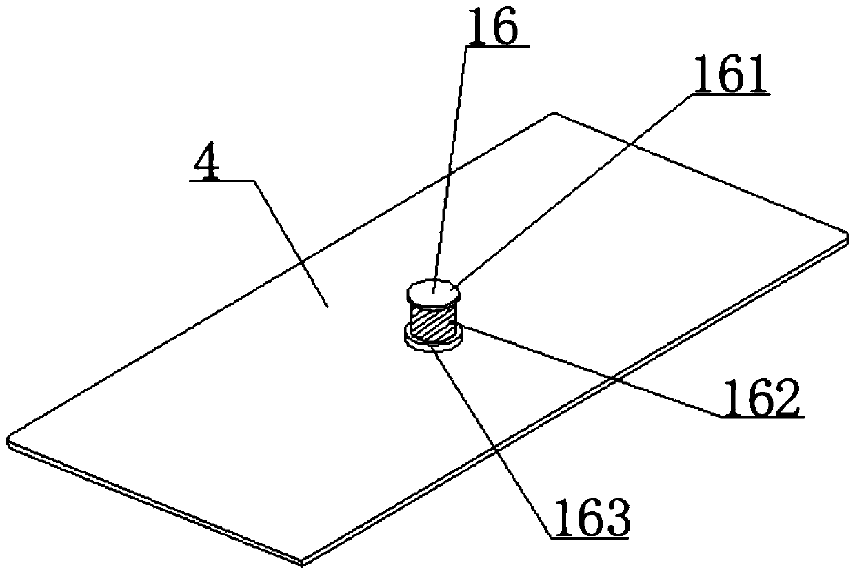
[0024] see Figure 1-4 , the present invention provides a technical solution for assembling a multi-layer optical fiber distribution frame:

[0025] An assembled multi-layer optical fiber distribution frame, including a distribution box body 2 and a front positioning slot plate 6, the front end of the distribution box body 2 is fixedly connected with the front positioning slot plate 6 by screw bolting, and the front positioning slot plate The front end face o...


PUM


Abstract

The invention discloses an assembled multilayer optical fiber distribution frame, comprising a distributing box body and a preposed locating trough plate, the front end of the distributing box body isbolted and fixedly connected with the preposed locating trough plate by virtue of screws, FC connection substrates are uniformly arranged at horizontal positions on the end surface of the front end of the preposed locating trough plate, the FC connection substrates penetrate to the end surface of the rear end of the preposed locating trough plate from the end surface of the front end of the preposed locating trough plate, the FC connection substrates are combined in a horizontal up-down arrangement mode, the front ends of the FC connection substrates are covered by virtue of a screwing protective cover, filter screen ventilation notches are formed at the two sides in the end surfaces of the left end and the right end of the distributing box body respectively, and the filter screen ventilation notches are longitudinally embedded into the wall bodies of the two sides from the end surfaces of the left end and the right end of the distributing box body, so that the phenomenon that large particulate matters such as dust enter the interior of the box body appears, effective dust prevention and water resistance can be realized, and both practicability and economy are excellent.

Description

technical field [0001] The invention belongs to the related technical field of optical fiber distribution frames, and in particular relates to an assembled multilayer optical fiber distribution frame. Background technique [0002] Optical fiber distribution frame is a wiring connection device between optical cable and optical communication equipment or between optical communication equipment. Optical fiber distribution frame is used for the termination and distribution of backbone optical cables in the optical fiber communication system, and can easily realize the connection of optical fiber lines. , allocation and scheduling. [0003] The existing optical fiber distribution frame technology has the following problems: At present, the two-way insertion slot of the optical fiber distribution frame is not covered, that is, when the optical fiber bus enters the body from the slot, there is no corresponding sealing device for the slot. Sealing the opening will easily cause a la...

Claims


Application Information

Patent Timeline
IPC IPC(8): G02B6/44
CPCG02B6/4452G02B6/4471G02B6/44384
Inventor 卢彭彭朱龙华王训荣
Owner 合肥昌嵩精密制造有限公司
Why Eureka
Try Eureka