
Optical switch control method and optical switch based on photonic crystal field resonance mode

A photonic crystal, resonant mode technology, applied in the field of optical switches, can solve problems such as hindering a wide range of applications, optical switch device integration, single optical path conduction, etc.

Active Publication Date: 2020-10-20
UNIVERSITY OF CHINESE ACADEMY OF SCIENCES
View PDF9 Cites 0 Cited by
  • Summary
  • Abstract
  • Description
  • Claims
  • Application Information

AI Technical Summary

Problems solved by technology

Traditional optical switches have problems such as excessive size and single optical path transmission. To obtain multiple beams of light, it is necessary to add corresponding beam splitting devices, and it is difficult to integrate optical switching devices into integrated optical circuits.
[0004] The intrinsic loss of metals in common micro-nano-scale optical switches hinders its wide application, and it is urgent to design a multifunctional optical switch device with small volume, low loss, low cost and high integration

Method used


Image

  • Optical switch control method and optical switch based on photonic crystal field resonance mode
  • Optical switch control method and optical switch based on photonic crystal field resonance mode
  • Optical switch control method and optical switch based on photonic crystal field resonance mode

Examples


Embodiment 1

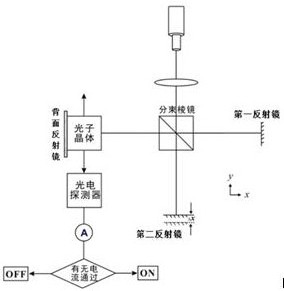
[0033] In order to meet the design requirements of sub-wavelength scale high-efficiency optical switch devices in photonic integrated optical circuits, this embodiment provides a field resonance mode-controlled symmetric radiation optical switch based on a square photonic crystal resonator, such as figure 1 As shown, it includes lasers, lenses, beam splitting prisms, mirrors, photonic crystal resonators, photodetectors and ammeters arranged in sequence. Using an optical path similar to the Michelson interferometer, the fixed optical path incident light (the first optical path) and the control light (the second optical path) are simultaneously incident on the square photonic crystal resonator vertically along the x-ray axis direction, and the photodetector and ammeter Electrically connected between them, placed on the radiation optical path of the photonic crystal resonator along the y-axis direction.

[0034] in particular:

[0035] The laser emits a beam of working frequency...

Embodiment 2

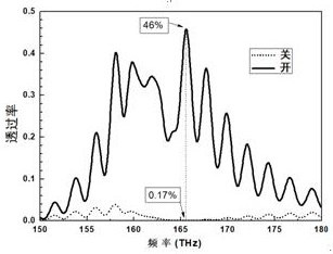
[0045] In order to further illustrate the different radiation transmittances of the photonic crystal resonator in embodiment 1 when the phase difference between the two incident lights is 0 and π respectively, this embodiment discloses that the phase difference between the two incident lights of the photonic crystal resonator is 0 and transmission characteristics at π.

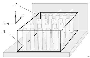
[0046] like figure 2 As shown, the photonic crystal-based field resonance mode of this embodiment controls the symmetrical radiation optical switch. Taking the terahertz band as an example, the photonic crystal resonator is composed of 20×20 high-refractive index dielectric columns 1, and the lattice period of the photonic crystal is 1μm×1μm, the radius of the dielectric column is 0.2μm, the dielectric column is made of a material with a dielectric constant of 12.5, the upper and lower metal plates and the polished back plate (polished metal mirror 2) as a mirror are made of Al material.

[0047] like imag...


PUM


Abstract

The invention discloses a photonic crystal field resonance mode-based optical switch control method and an optical switch. According to the method, two beams of incident light are vertically emitted to a photonic crystal resonator with a linear dispersion characteristic simultaneously along the same optical axis direction; the first incident light is fixed incident light; the second incident lightis dynamic phase-adjustable incident light; the two beams of incident light are subjected to field resonance superposition in the photonic crystal resonator after being reflected, and symmetrical radiation light beams are generated in a direction perpendicular to an incident optical axis; the phase of the second incident light beam can be adjusted, so that phase difference between the two incident light beams is controlled to be 0 or pi, and therefore, the on-off state of the symmetrical radiation light beams of the photonic crystal resonator is achieved. The optical switch comprises a laser,a lens, a beam splitter prism and a photonic crystal resonator; a reflector is arranged in the beam splitting direction of the beam splitter prism; and the photonic crystal resonator is vertically arranged on the optical axis of the two beams of incident light which have been combined. The working wavelength of the optical switch is selectable; the integration level of the optical switch is high;and the optical switch integrates the functions of optical switches and beam splitters.

Description

technical field [0001] The invention relates to an optical switch controlled by a field resonance mode based on a photonic crystal resonator, and belongs to the technical field of optical switches. Background technique [0002] With the development of optical communication and optical information technology, optical devices are developing towards miniaturization and integration. As the basic unit of data transmission and information exchange, optical switch is of great significance to the development of optical communication and optical information technology towards integration. [0003] The main function of the optical switch is to realize the rapid switching between the two states of the presence or absence of optical signals or parameters such as power and phase under controllable conditions. Traditional optical switches have problems such as excessive size and single optical path transmission. To obtain multiple beams of light, additional corresponding beam splitting d...

Claims


Application Information

Patent Timeline
IPC IPC(8): G02B6/12G02B6/122
CPCG02B6/12G02B6/1225G02B2006/12145
Inventor 董国艳乔鹏武郑姝慧
Owner UNIVERSITY OF CHINESE ACADEMY OF SCIENCES
Learn More