Method of manufacturing motor rotor and motor rotor

A technology of a motor rotor and a manufacturing method, which is applied in the manufacture of stator/rotor body, magnetic circuit rotating parts, magnetic circuit shape/style/structure, etc., can solve problems such as poor production efficiency, and achieve the effect of improving low production efficiency

Active Publication Date: 2019-11-26
KAORI HEAT TREATMENT COMPANY
View PDF7 Cites 0 Cited by
  • Summary
  • Abstract
  • Description
  • Claims
  • Application Information

AI Technical Summary

Problems solved by technology

[0003] The main purpose of the present invention is to provide a method for manufacturing a motor rotor, which is used to improve the poor production efficiency of the motor rotor to be processed in a vacuum furnace in the prior art.

Method used


Image

  • Method of manufacturing motor rotor and motor rotor
  • Method of manufacturing motor rotor and motor rotor
  • Method of manufacturing motor rotor and motor rotor

Examples


Embodiment Construction

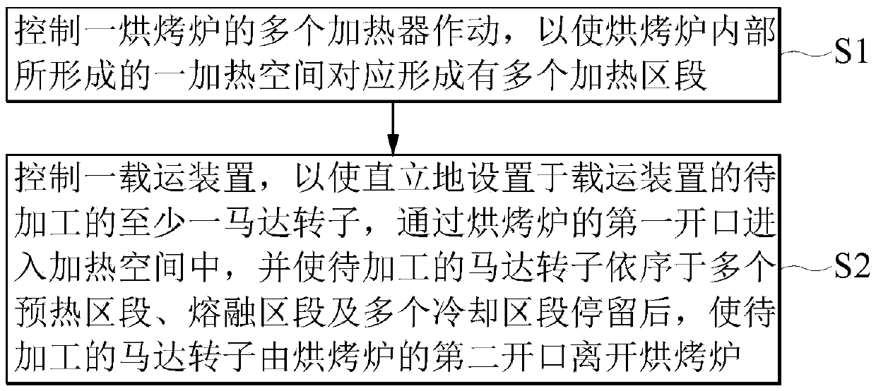
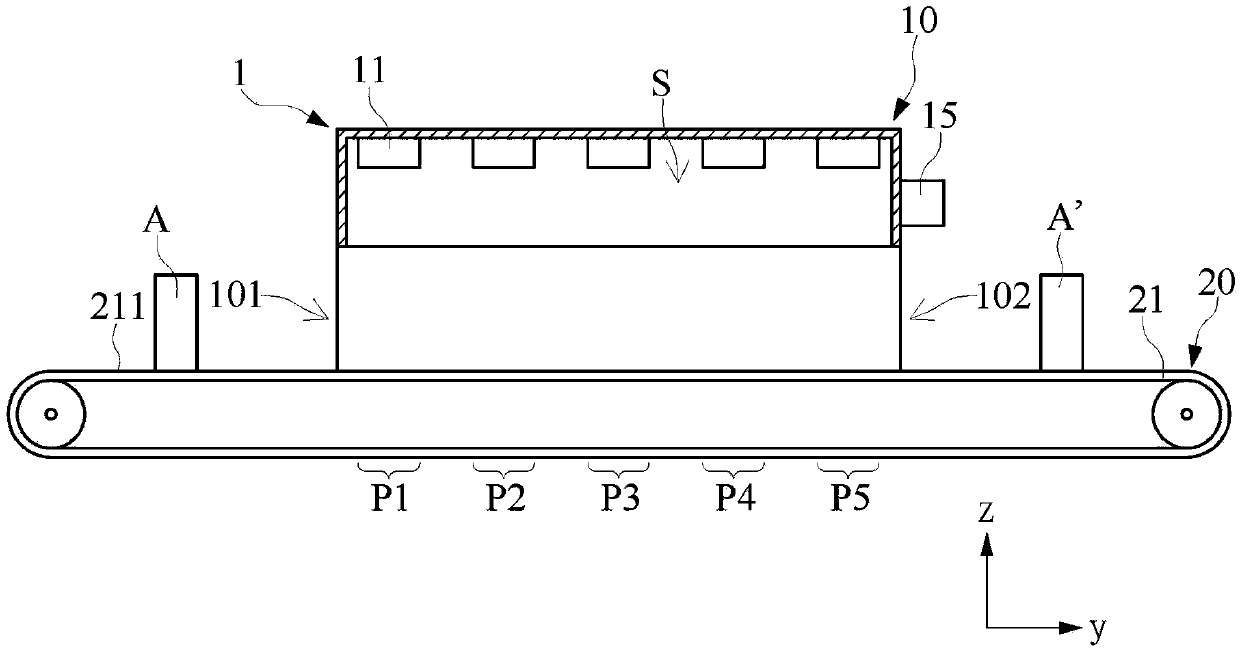
[0030] Please also refer to figure 1 and figure 2 , figure 1 It is a schematic flow chart of the manufacturing method of the motor rotor of the present invention, figure 2 It is a schematic diagram of the baking furnace mentioned in the manufacturing method of the motor rotor of this invention. Such as figure 1 As shown, the manufacturing method of the motor rotor of the present invention comprises the following steps:

[0031] A preparatory step S1: controlling the operation of multiple heaters of a baking oven, so that a heating space formed inside the baking oven is correspondingly formed with a plurality of heating zones.

[0032] A heating step S2: controlling a carrying device so that at least one motor rotor to be processed vertically arranged on the carrying device enters the heating space through the first opening of the oven, and makes the motor rotor to be processed sequentially After staying in a preheating section, a melting section and a plurality of cooling...


PUM


Abstract

A method of manufacturing a motor rotor includes a preparation step and a heating step. The preparation step comprises actuating a plurality of heaters of a baking furnace so as to correspondingly form a plurality of heating sections in a heating space formed in the baking furnace. The heating step comprises controlling a transport device such that at least one motor rotor to be processed and vertically arranged on the transport device enters the heating space through a first opening, and leave the heating space through a second opening after successively residing in a plurality of preheatingsections, a melting section and a plurality of cooling sections. The method of manufacturing the motor rotor of the present invention does not need an air exhaust operation before heating the motor rotor, thereby solving the low production efficiency of a known method where heating the motor rotor by a vacuum furnace requires a large amount of time for a vacuum operation.

Description

technical field [0001] The invention relates to a method for manufacturing a motor rotor and the motor rotor, in particular to a method for manufacturing a motor rotor mainly made of copper material and the motor rotor mainly made of copper material. Background technique [0002] The existing method of using a vacuum furnace to heat the motor rotor to connect the related solder of the motor rotor with its corresponding structure has many problems in actual implementation. For example, before the vacuum furnace is heated, it must be vacuumized first, and then the heating operation can be performed. Therefore, when performing mass production operations, it takes a lot of time to use the vacuum furnace to heat the motor rotor. . In addition, if the related industry wants to increase the number of motor rotors carried by the vacuum furnace at one time, the vacuum furnace must be enlarged, which will lead to an increase in the purchase cost of the vacuum furnace. In view of thi...

Claims


Application Information

Patent Timeline
Patent Type & Authority Applications(China)
IPC IPC(8): H02K15/02H02K1/22H02K1/32
CPCH02K1/22H02K1/32H02K15/02
Inventor 陈建和李青峻李俊颖王琬琦
Owner KAORI HEAT TREATMENT COMPANY
Why Eureka
Try Eureka