Spliced display system and signal control method thereof

A splicing display and signal control technology, applied in signal transmission system, digital output to display equipment, image communication, etc., can solve the problems of low manual operation efficiency, low reliability, cumbersome LED display wiring, etc., and achieve high reliability , fast response speed, and improved screen loading efficiency

Inactive Publication Date: 2019-11-26
SHENZHEN LAMP TECH +1
View PDF4 Cites 12 Cited by
  • Summary
  • Abstract
  • Description
  • Claims
  • Application Information

AI Technical Summary

Problems solved by technology

[0003] The main purpose of the present invention is to propose a splicing display system and its signal control method, which aims to solve the complicated wiring of the existing LED display screen, the low efficiency of manual operation, and the display of the display screen is easily affected by a single box, wire, connector, etc. Problems such as low reliability caused by failure effects

Method used


Image

  • Spliced display system and signal control method thereof
  • Spliced display system and signal control method thereof
  • Spliced display system and signal control method thereof

Examples


Embodiment 1

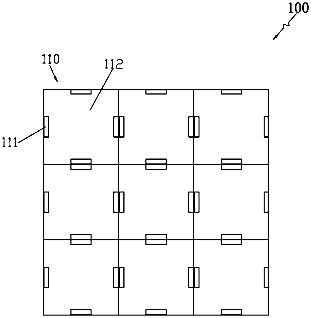
[0025] Such as figure 1 As shown, Embodiment 1 of the present invention provides a splicing display system, the splicing display system includes a display array 110, the display array 100 includes a number of LED display units 110 spliced ​​together, and each LED display unit 110 includes a number of wireless transmission Module 111 , two-way signal transmission between two adjacent LED display units 110 through a group of adjacent paired wireless transmission modules 111 , so as to form a grid-type signal transmission network in the display array 110 .

[0026] In this embodiment, the wireless transmission module 111 specifically includes a sending unit and a receiving unit. The sending unit and the receiving unit can transmit signals and data wirelessly in short-distance point-to-point. The short-distance point-to-point wireless transmission can be electromagnetic transmission or optical transmission. The wireless transmission module 111 includes, but is not limited to, any ...

Embodiment 2

[0031] Such as Figure 4 As shown, Embodiment 2 of the present invention proposes a signal control method, based on the splicing display system 100 of Embodiment 1 above, the signal control method specifically includes the following steps:

[0032] Step S110: Automatically switch the signal input of the display array according to the working condition of the main signal source unit.

[0033] Specifically, as shown in 5, a plurality of LED display units 110 are spliced ​​into a 3*3 display array 100, signal A is the main signal, and signal B is the backup signal. Two adjacent LED display units 110 conduct bidirectional signal transmission through a group of adjacent paired wireless transmission modules 111 , so as to form a grid-type signal transmission network in the display array 100 . The system automatically assigns a corresponding address to each LED display unit 110 based on the location of each LED display unit 110 .

[0034] Such as Figure 6 As shown, the specific p...


PUM


Abstract

The invention discloses a spliced display system and a signal control method thereof, and belongs to the technical field of LED display screens. The spliced display system comprises a display screen array, wherein the display screen array comprises a plurality of LED display units which are spliced together. Each LED display unit comprises a plurality of wireless transmission modules, and two-waysignal transmission is carried out between every two adjacent LED display units through a group of adjacently paired wireless transmission modules, so that a grid type signal transmission network is formed in the display screen array. According to the technical scheme, the problems that an existing LED display screen is complex in wiring and low in manual operation efficiency, display of the display screen is prone to being affected by faults of a single box body, a single wire, a single connector and the like, and consequently reliability is low can be effectively solved.

Description

technical field [0001] The invention relates to the technical field of LED display screens, in particular to a splicing display system and a signal transmission method thereof. Background technique [0002] In the current LED display, data transmission between cabinets is usually carried out through wires (such as network cables, aviation plug-in cables, HDMI cables and BNC cables, etc.). After manual wiring, the data transmission path between the cabinets generally forms a "Z" or "N" shape on the display screen. However, the above method has the following disadvantages: 1. The manual wiring operation is more complicated and inefficient; 2. When a certain cabinet or a certain wire of the display screen fails, it will often cause a row or a row of cabinets or even the entire display screen to fail to display normally. ; 3. The data transmission of the display screen is easily affected by a certain wire or connector. The display screen that needs data signal backup needs two ...

Claims


Application Information

Patent Timeline
Patent Type & Authority Applications(China)
IPC IPC(8): G06F3/14G08C17/02H04N21/4363
CPCG06F3/1446G08C17/02H04N21/43637
Inventor 王朝王爱武李全波汪志南
Owner SHENZHEN LAMP TECH
Why Eureka
Try Eureka