


Quick Research
Generate reliable direction feasibility study reports for your R&D in just a few steps.

Technical Q&A
Discover and master advanced knowledge NOW. Basics, ideas, possibilities, all at once.

Find Solutions
As an expert in R&D theories, this can generate solutions to your technical problems instantly.

Evaluate Feasibility
Analyze your overall solution with one click, know your potential R&D risks in advance.

Monitor Landscape
Get weekly tech updates, stay abreast of the latest tech innovations and key insights.
Millimeter wave antenna
A millimeter wave, antenna technology, applied in the direction of antennas, resonant antennas, electrical short antennas, etc., can solve the problems of radiation pattern distortion, poor operating performance, preventing the application of antenna arrays, etc., to achieve the effect of easy manufacturing
- Summary
- Abstract
- Description
- Claims
- Application Information
AI Technical Summary
Problems solved by technology
Method used
Image

Examples
Embodiment Construction
[0037] Embodiments will now be described with reference to the drawings, wherein like reference numerals are used to refer to like elements throughout. It will be understood that the drawings are not necessarily to scale. Features described and / or illustrated with respect to one embodiment may be used in the same or similar manner in one or more other embodiments and / or in combination with or instead of features of other embodiments.
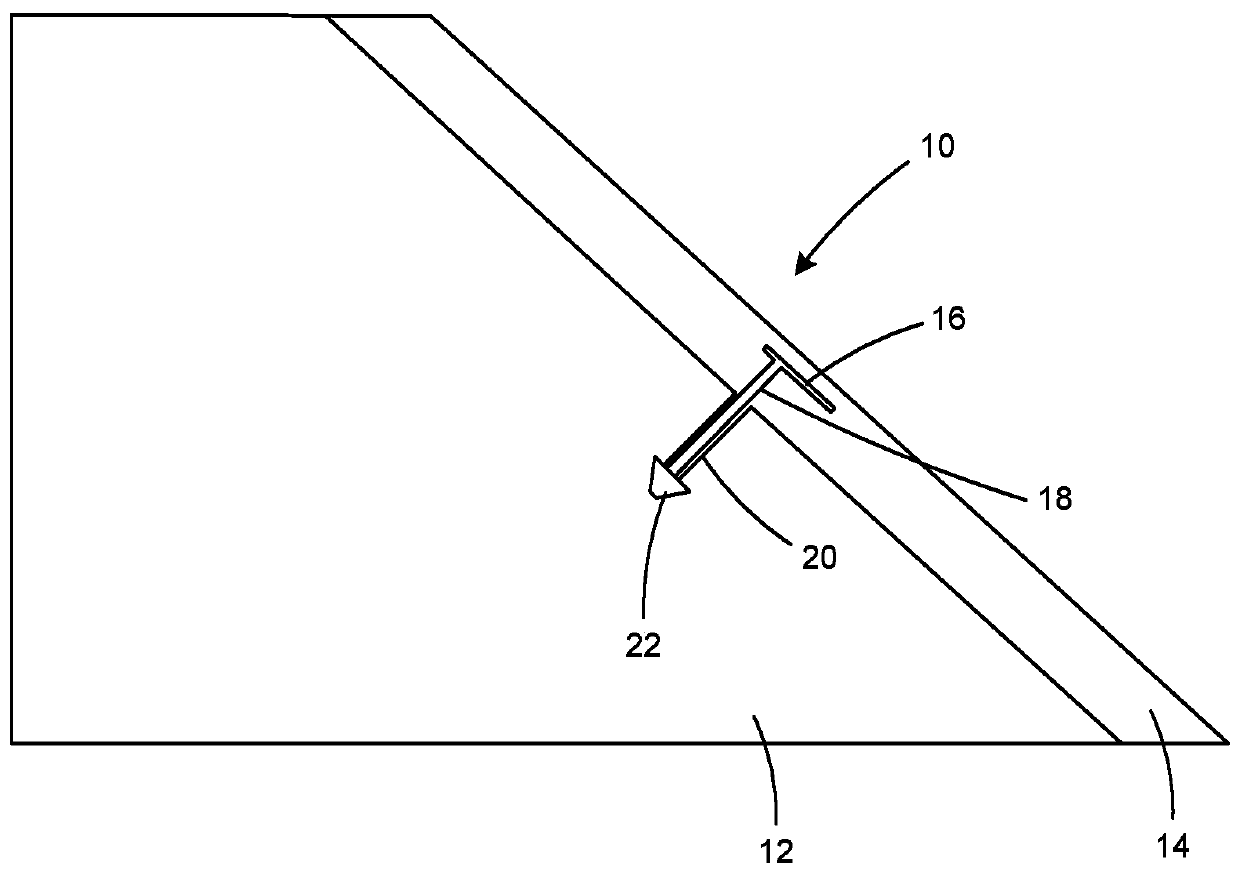
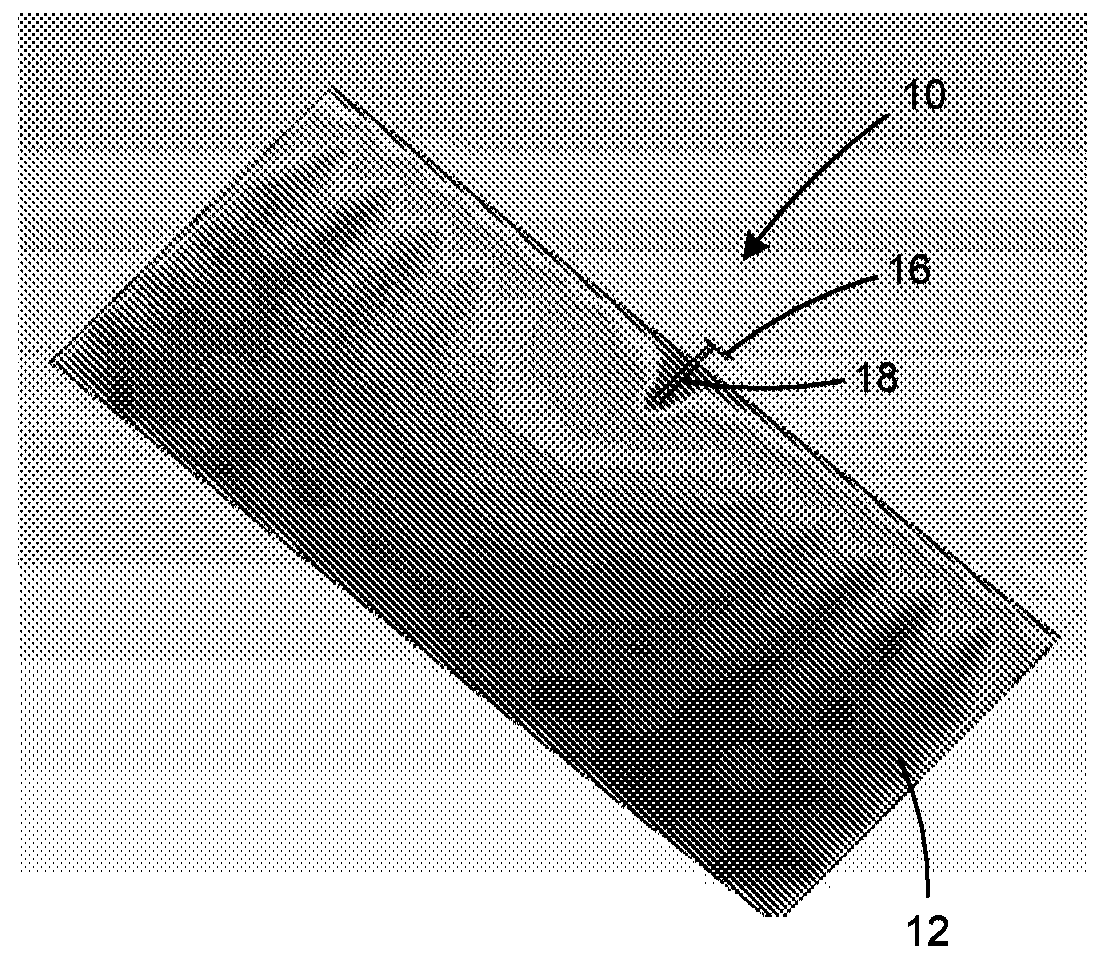
[0038] Described below with reference to the accompanying drawings are various embodiments of antenna structures that may be used with a mobile terminal, such as a mobile phone. While the figures illustrate one antenna, it will be understood that a mobile terminal may include an array of antennas for beamforming or scanning applications.
[0039] refer to Figure 4 , illustrating an exemplary environment for the disclosed antenna. An exemplary environment is an electronic device 24 configured as a mobile wireless telephone (more commonly refer...
PUM
 Abstract
Description
Claims
Application Information
 - R&D Engineer
- R&D Manager
- IP Professional
- Industry Leading Data Capabilities
- Powerful AI technology
- Patent DNA Extraction
Browse by: Latest US Patents, China's latest patents, Technical Efficacy Thesaurus, Application Domain, Technology Topic, Popular Technical Reports.
© 2024 PatSnap. All rights reserved.Legal|Privacy policy|Modern Slavery Act Transparency Statement|Sitemap|About US| Contact US: help@patsnap.com