
Special-shaped groove stator punching sheet of motor

A stator punching, special-shaped slot technology, applied in the direction of electric components, electrical components, electromechanical devices, etc., can solve the problems of small motor output power, large winding span distance, uneven magnetic density distribution, etc., to reduce the overall magnetic loss. , Reduce the winding span distance, reduce the leakage coefficient and the effect of temperature rise

Inactive Publication Date: 2019-11-22
合肥市通得力电气制造有限公司 +1
View PDF0 Cites 0 Cited by
  • Summary
  • Abstract
  • Description
  • Claims
  • Application Information

AI Technical Summary

Problems solved by technology

[0002] The punching body of the traditional motor stator punching generally has 24 single-layer punching slots distributed uniformly along the radial and circumferential direction. After magnetic circuit analysis and calculation, this stator punching structure has the following disadvantages: 1. Due to the structural space Due to the limitation, the width of the tooth part is small, which leads to the saturation of the magnetic density of the tooth part of the punching sheet, while the magnetic density of the yoke part is small, and the distribution of the magnetic density is uneven, resulting in low motor efficiency; 2. This kind of punching sheet adopts the traditional According to the electromagnetic theory calculation, the winding span distance is relatively large, the amount of enameled wire is relatively large, and the cost is relatively high; 3. Due to the limited space and structural space of this kind of punching sheet, the slot area of ​​the motor is small, and the output power of the motor is small. And the qualification rate is low, and the indirect cost is high

Method used


Image

  • Special-shaped groove stator punching sheet of motor
  • Special-shaped groove stator punching sheet of motor
  • Special-shaped groove stator punching sheet of motor

Examples


Embodiment Construction

[0025] In order to make the technical means, creative features, goals and effects achieved by the present invention easy to understand, the technical solutions in the embodiments of the present invention will be clearly and completely described below in conjunction with the accompanying drawings in the embodiments of the present invention. Obviously, the The described embodiments are only some, not all, embodiments of the present invention. Based on the embodiments of the present invention, all other embodiments obtained by persons of ordinary skill in the art without creative efforts fall within the protection scope of the present invention.

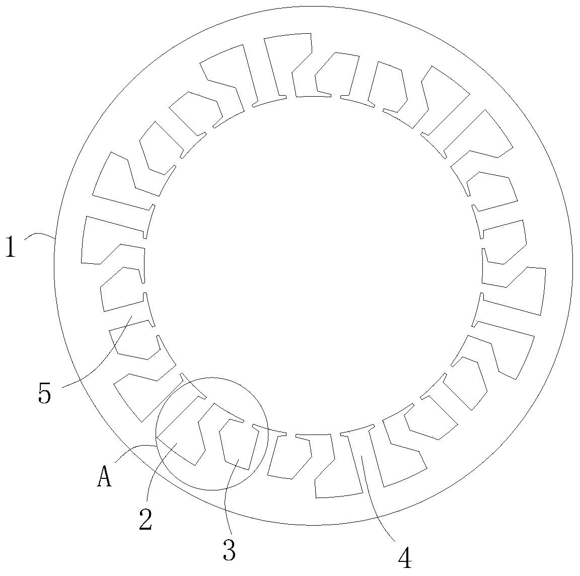
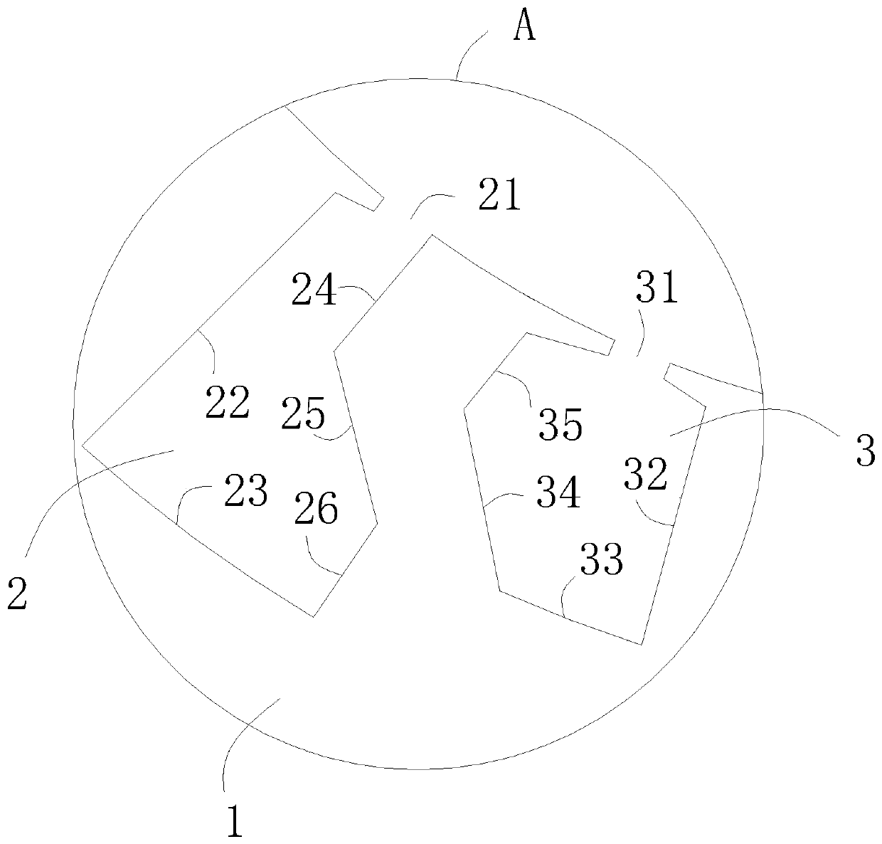
[0026] see Figure 1-2 , Figure 1-2 It shows a special-shaped slot stator stamping of a motor, including a body 1 of the stator stamping. The body 1 is provided with two layers of stamping grooves in the radial direction, which are respectively defined as the outer stamping groove 2 and the inner stamping groove 3,

[0027] Wherein ...


PUM


Abstract

The invention relates to the technical field of motor accessories, in particular to a special-shaped groove stator punching sheet of a motor, which comprises a stator punching sheet body; two layers of punching sheet grooves are arranged on the body and are respectively defined as an outer punching sheet groove and an inner punching sheet groove, and the outer punching sheet groove is arranged onthe body and comprises a first notch, a first straight groove body, a first groove bottom and a first special-shaped groove body; the inner punching sheet groove is formed in the body and comprises asecond notch, a second straight groove body, a second groove bottom and a second special-shaped groove body. The motor has the beneficial effects that the stator adopts a double-layer special-shaped groove design, so that the utilization rate of the punching sheet space is increased, and the groove area of the punching sheet is increased; the width size of a tooth part of the punching sheet is increased, the width size of a yoke part is locally reduced, the flux density of the yoke part is locally increased, yet the flux density of the tooth part and the flux density of an air gap are reduced,the overall flux density is reduced, the overall magnetic loss is reduced, and the motor efficiency is improved.

Description

technical field [0001] The invention relates to the technical field of motor accessories, in particular to a stamped sheet of a stator with a special-shaped slot for a motor. Background technique [0002] The punching body of the traditional motor stator punching generally has 24 single-layer punching slots distributed uniformly along the radial and circumferential direction. After magnetic circuit analysis and calculation, this stator punching structure has the following disadvantages: 1. Due to the structural space Due to the limitation, the width of the tooth part is small, which leads to the saturation of the magnetic density of the tooth part of the punching sheet, while the magnetic density of the yoke part is small, and the distribution of the magnetic density is uneven, resulting in low motor efficiency; 2. This kind of punching sheet adopts the traditional According to the electromagnetic theory calculation, the winding span distance is relatively large, the amount ...

Claims


Application Information

Patent Timeline
Patent Type & Authority Applications(China)
IPC IPC(8): H02K1/14H02K1/16
CPCH02K1/146H02K1/16H02K2213/03
Inventor 董小振张四生姚翔
Owner 合肥市通得力电气制造有限公司
Learn More