
Solid-state transformer topology family applied to alternating-current and direct-current hybrid power distribution network and design method

A technology of solid-state transformer and distribution network, which is applied in the direction of power transmission AC network, conversion of AC power input to DC power output, and conversion of DC power input to DC power output, etc., which can solve the problem of increasing device cost and large current stress of MMC switching devices and other issues, to achieve the effect of reducing current stress, low cost, and high degree of modularization

Inactive Publication Date: 2019-11-22
SHANGHAI JIAO TONG UNIV
View PDF5 Cites 11 Cited by
  • Summary
  • Abstract
  • Description
  • Claims
  • Application Information

AI Technical Summary

Problems solved by technology

Compared with the three-phase half-bridge cascaded power electronic transformer, this topology improves the quality of the DC output voltage and significantly reduces the amount of high-frequency transformers and power electronic switching devices, but the medium-voltage network and low-voltage network of this topology need to pass through Medium-voltage DC bus for power transfer, resulting in high current stress on MMC switching devices
In addition, additional series capacitors are required on the medium-voltage DC bus to realize MMC and DAB, which increases the cost of the device
Therefore, there is a large room for optimization in this topology

Method used


Image

  • Solid-state transformer topology family applied to alternating-current and direct-current hybrid power distribution network and design method
  • Solid-state transformer topology family applied to alternating-current and direct-current hybrid power distribution network and design method
  • Solid-state transformer topology family applied to alternating-current and direct-current hybrid power distribution network and design method

Examples


Embodiment Construction

[0049] The present invention will be described in detail below with reference to specific embodiments. The following examples will help those skilled in the art to further understand the present invention, but do not limit the present invention in any form. It should be noted that, for those skilled in the art, several modifications and improvements can be made without departing from the concept of the present invention. These all belong to the protection scope of the present invention.

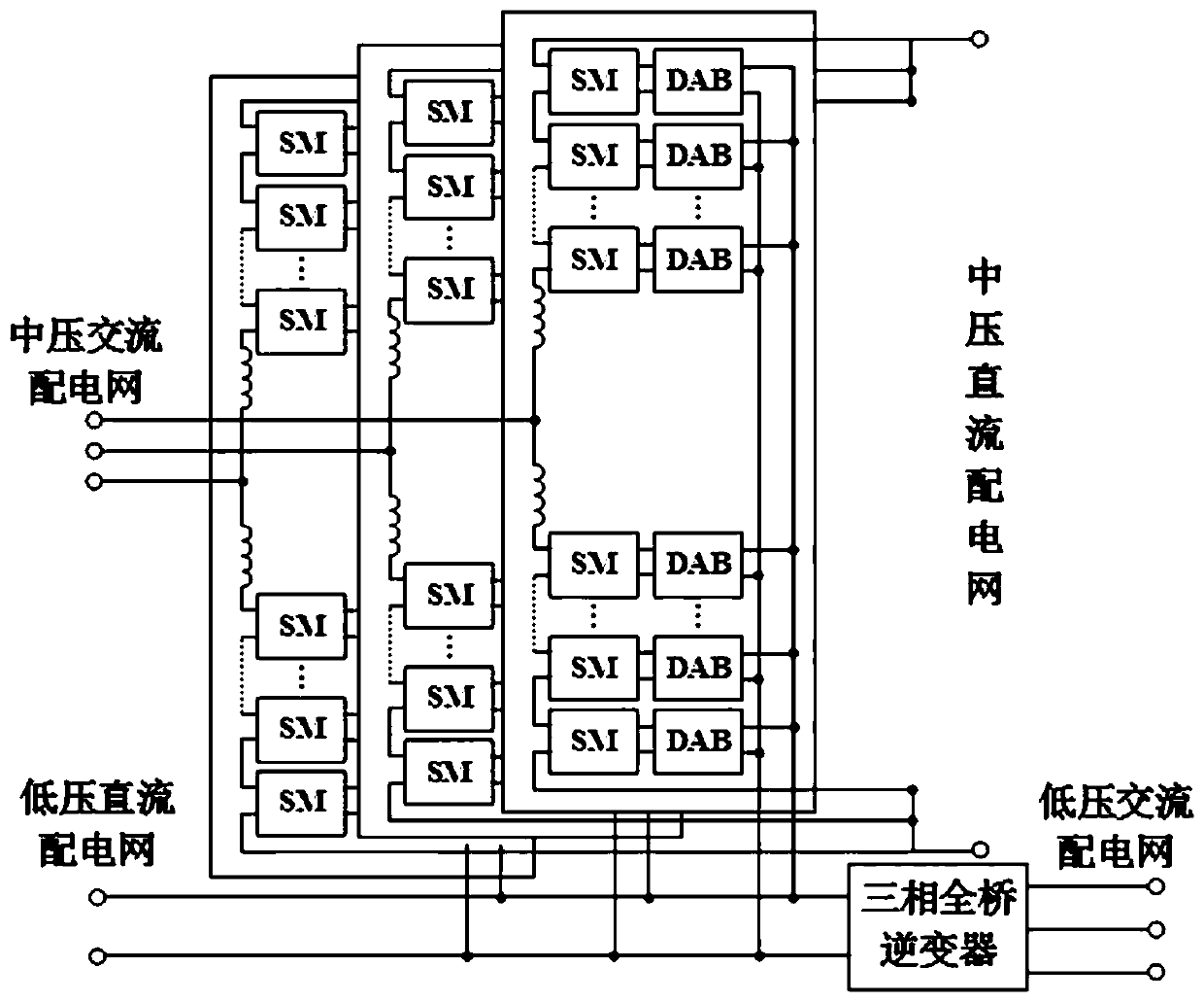
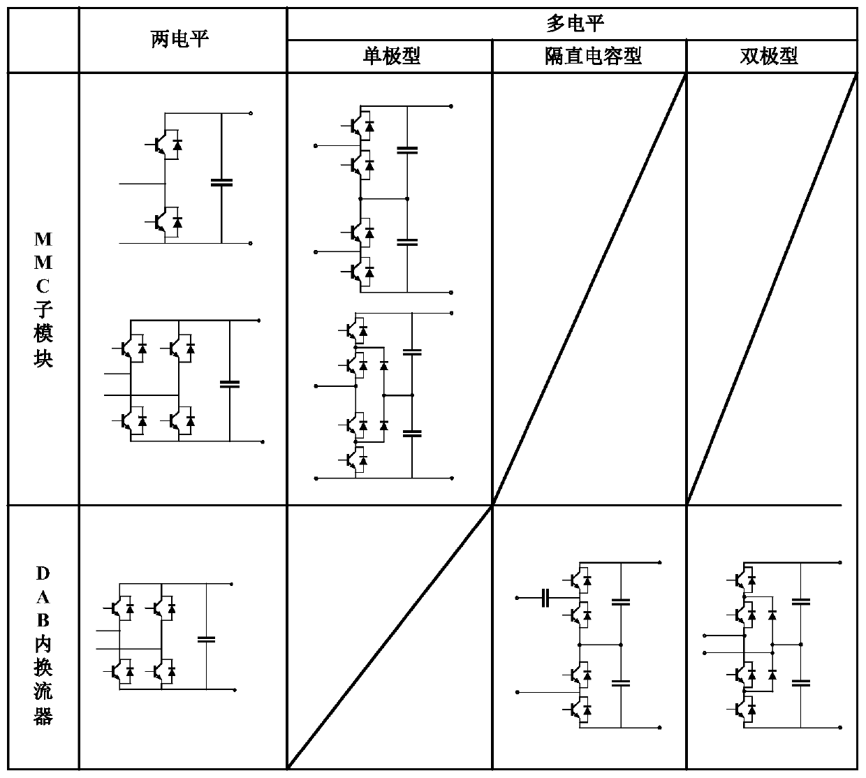
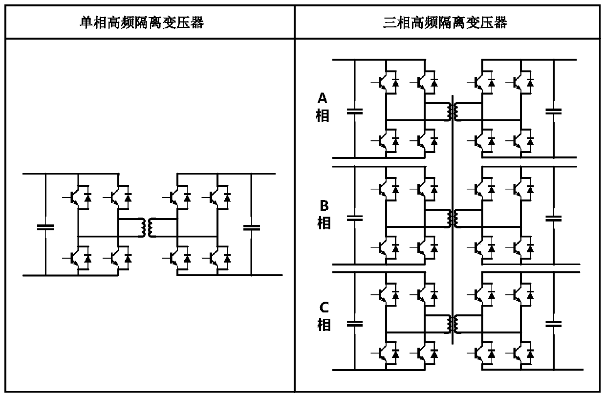
[0050] The embodiment of the present invention proposes a solid-state transformer topology family applied to the AC-DC hybrid distribution network. The topology family performs power transfer between medium and low-voltage networks through the DC side of the sub-modules, reducing the need for modular multilevel converters (MMCs). ) bridge arm DC component, which optimizes the switch stress; the sub-module unit of the modular multilevel converter (MMC) and the isolated dual active bridge conv...


PUM


Abstract

The invention provides a solid-state transformer topology family applied to a direct-current and alternating-current hybrid power distribution network. The direct-current end of a sub-module of a modular multilevel converter and the input end of each isolated dual-active-bridge converter are interconnected to form a modular structure, the output ends of the multiple isolated dual-active-bridge converters are connected in parallel to form a low-voltage direct-current bus, and a three-phase full-bridge inverter is connected to the low-voltage direct-current bus to provide medium-voltage direct-current, medium-voltage alternating-current, low-voltage direct-current and low-voltage alternating-current ports, so the four kinds of ports are suitable for interconnection of multi-voltage-level polymorphic alternating-current and direct-current hybrid power distribution networks. The invention further provides a design method of the solid-state transformer topology family, so that the number ofsub-modules and the number of high-frequency transformers in the solid-state transformer device are reduced on the premise of obtaining the solid-state transformer device meeting specific scene requirements, and the size and the cost are reduced.

Description

technical field [0001] The invention relates to the fields of intelligent distribution network technology and power electronics technology in power systems, and in particular relates to a modular solid-state transformer topology family and design method applied to an AC-DC hybrid distribution network. Background technique [0002] The future power distribution system has the characteristics of high proportion of distributed power supply and flexible load (electric vehicle, distributed energy storage) access, high power quality of users and customization requirements of various power forms, and the proposal of ubiquitous electric power Internet of things makes The new-generation energy system with the grid as the core and the efficient integration of multiple energy sources puts forward higher requirements for the flexibility, controllability and resilience of the distribution network. However, the operation mode of the traditional distribution network is basically based on t...

Claims


Application Information

Patent Timeline
IPC IPC(8): H02J3/36H02J5/00H02M7/797H02M3/335H02M7/483H02M7/487
CPCH02J3/36H02J5/00H02M3/33584H02M7/483H02M7/487H02M7/797H02M1/007Y02E60/60
Inventor 张建文章一新施刚周剑桥蔡旭
Owner SHANGHAI JIAO TONG UNIV
Learn More