Acoustic vortex field detector based on Fraunhofer diffraction principle
A diffraction principle and Fraunhofer's technology, applied in the field of acoustic vortex field detectors based on the Fraunhofer diffraction principle, can solve the problems of large size and limited application, and achieve a simple method, easy implementation, and easy structure Effect
- Summary
- Abstract
- Description
- Claims
- Application Information
AI Technical Summary
Problems solved by technology
Method used
Image

Examples
Embodiment 1
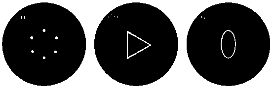
[0029] Such as figure 1 As shown in (a), including the substrate with a circular diffraction hole, the number of circular holes in the diffraction hole is N=6, and the incident acoustic vortex wave travels for a certain distance and reaches figure 1 (a) This circular hole array diffraction screen, after passing through the diffraction screen and then propagating for a certain distance, extracts the intensity distribution of the sound field. The theoretical calculation process is as follows:
[0030] The sound field at any point in the acoustic vortex field can be used said, among them is the amplitude and l is the topological charge. The intensity distribution obtained after passing through the multi-hole interference screen is
[0031] (1)
[0032] in, and c are the density and sound velocity of the background medium. For the topological charge of the incident acoustic vortex field is l, the intensity distribution diagram of the interference screen passing throug...
Embodiment 2
[0041] Such as figure 1 As shown in (b), including the substrate whose diffraction hole is an annular triangular hole structure, when the incident sound wave is a vortex wave, the wave field expression on the plane of the annular triangular hole (z=0) is:
[0042] (4)
[0043] where l is the topological charge, is the coordinates in the plane of the triangular hole; is the beam waist size of the vortex sound beam irradiated on the triangular hole.
[0044] When the vortex sound beam is irradiated on the annular triangular hole diffraction screen, the expression of the sound field in the Fraunhofer diffraction area is:
[0045] (5)
[0046] in is the transmittance function.
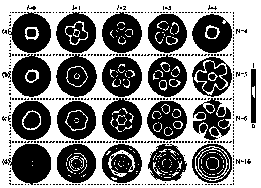
[0047] for figure 1(b) The simulated intensity distribution diagram obtained by the simulation of this structure is as follows: Figure 4 shown. for Figure 4 , when the frequency is 300kHz, for Figures (a), (c), (d), (h) the outer side length of the annular triangular hole diffraction s...
Embodiment 3
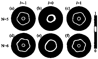
[0049] Such as figure 1 As shown in (c), the substrate including the diffraction hole is an annular ellipse structure, and its theoretical derivation is the same as that of the annular triangular hole diffraction screen. Simulate this structure directly. At a frequency of 300kHz, figure 1 (c) This annular elliptical hole diffraction screen is designed such that the major axis and minor axis of the outer ring are 2.3mm and 1.8mm respectively, and the major axis and minor axis of the inner ring are 1.84mm and 1.44mm respectively. Simulation results such as Figure 5 shown.
[0050] From simulation results Figure 5 It can be seen that when the topological charge of the incident acoustic vortex is 1, there is a dark spot in the center of the intensity distribution, and a singularity in the center of the phase distribution; when the topological charge of the incident acoustic vortex is 2, there are two spots in the center of the intensity distribution. A dark spot with two si...
PUM
| Property | Measurement | Unit |
|---|---|---|
| Density | aaaaa | aaaaa |
| Radius | aaaaa | aaaaa |
Abstract
Description
Claims
Application Information
 - R&D
- Intellectual Property
- Life Sciences
- Materials
- Tech Scout
- Unparalleled Data Quality
- Higher Quality Content
- 60% Fewer Hallucinations
Browse by: Latest US Patents, China's latest patents, Technical Efficacy Thesaurus, Application Domain, Technology Topic, Popular Technical Reports.
© 2025 PatSnap. All rights reserved.Legal|Privacy policy|Modern Slavery Act Transparency Statement|Sitemap|About US| Contact US: help@patsnap.com