
Fixing device of floating slab track supporting structure

A supporting structure and fixing device technology, applied in the direction of tracks, roads, ballast layers, etc., can solve the problems of affecting continuity, increasing the complexity of force transmission mechanism, and cumbersome assembly process, so as to improve installation efficiency and facilitate maintenance and replacement work Effect

Pending Publication Date: 2019-11-22
TONGJI UNIV
View PDF0 Cites 1 Cited by
  • Summary
  • Abstract
  • Description
  • Claims
  • Application Information

AI Technical Summary

Problems solved by technology

The leveling steel plate is placed between the inner and outer sleeves to adjust the elevation of the track bed, but at the same time it affects the continuity between the inner and outer sleeves, and increases the complexity of the force transmission mechanism, making the assembly process cumbersome

Method used


Image

  • Fixing device of floating slab track supporting structure
  • Fixing device of floating slab track supporting structure
  • Fixing device of floating slab track supporting structure

Examples


Embodiment

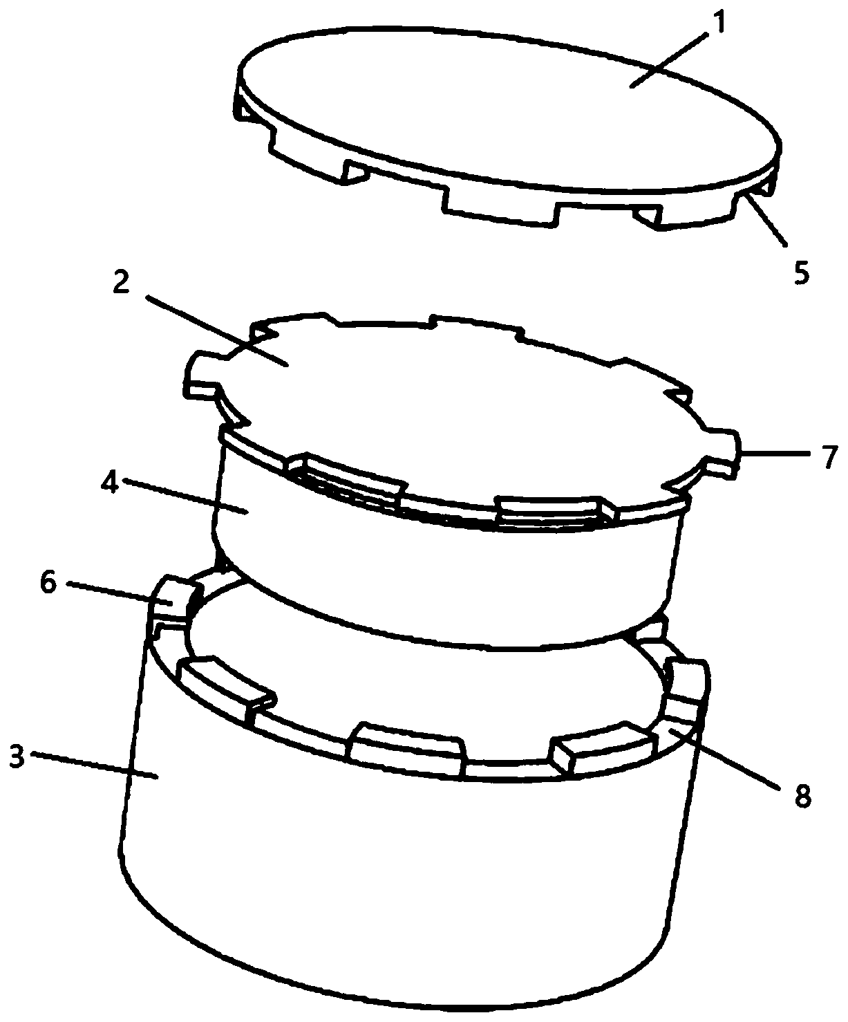
[0030] The fixing device for the support structure of the floating plate track in this embodiment includes a sleeve 3, a toothed disc 3 and a cover plate 1, see figure 1 .

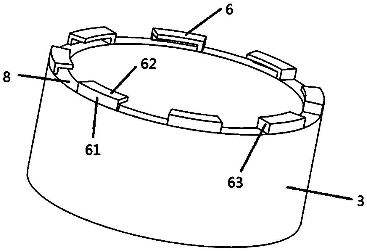
[0031] Sleeve 3: it is set on the support structure 4, see figure 1 , the bottom end of the sleeve 3 is pressed against the foundation, the middle part and the top end are arranged inside the floating plate track, and the top end is evenly distributed along the circumferential direction with a plurality of raised L-shaped clamping plates 6, the L-shaped clamping plates 6, and the top of the sleeve 3 An L-shaped groove with a horizontal opening is formed between the upper edges, and a positioning opening 8 is formed between adjacent L-shaped clamping plates 6 . The L-shaped clamping board includes a first vertical surface 61, a second vertical surface 62 and a third vertical surface 63, see figure 2 . The first elevation 61 is parallel to the axis of the sleeve 3, one side of the first elevation 61 is c...


PUM


Abstract

The invention relates to a fixing device of a floating slab track supporting structure. The fixing device comprises a sleeve, a fluted disc and a cover plate, wherein the sleeve sleeves the supportingstructure, the bottom end of the sleeve abuts against the foundation, and the middle and the top end of the sleeve are arranged in a floating slab track; a plurality of protruding L-shaped clamping plates are evenly distributed at the top end of the sleeve in the circumferential direction, L-shaped grooves with horizontal openings are formed between the L-shaped clamping plates and the upper edgeof the top of the sleeve, and a positioning opening is formed between the adjacent L-shaped clamping plates; a plurality of convex claws are arranged at the edge of the fluted disc and can be clampedinto the positioning openings, and the convex claws are meshed with the L-shaped grooves by horizontally rotating the fluted disc; a plurality of clamping grooves are formed at the edge of the lowersurface of the cover plate, and when the cover plate covers the top of the sleeve, the L-shaped clamping plates are engaged with the clamping grooves. Compared with the prior art, the supporting structure is not prone to lateral displacement, through the sleeve and the fluted disc, the mounting efficiency of the floating slab track supporting structure is greatly improved; the rotation of the fluted disc is limited through the cover plate, so that the influence of the external sundries on the internal supporting structure can be reduced.

Description

technical field [0001] The invention relates to the field of rail traffic vibration reduction and noise reduction, in particular to a fixing device for a floating plate rail support structure. Background technique [0002] As the environmental vibration problem caused by urban rail transit becomes more and more prominent, various floating slab track support structures emerge in an endless stream, but the devices for assembling these various support structures inside the floating slab track structure are very scarce. [0003] At present, the fixing device of the track support structure of the floating slab consists of two parts, a leveling steel plate and an inner and outer sleeve. The leveling steel plate is arranged between the inner and outer sleeves to control the elevation. During construction, the outer sleeve is cast into a concrete deck, which transmits the forces on the deck to the inner sleeve. The inner sleeve consists of helical steel springs and dampers that tra...

Claims


Application Information

Patent Timeline
Patent Type & Authority Applications(China)
IPC IPC(8): E01B1/00
CPCE01B1/002E01B2204/09E01B2204/12
Inventor 金浩李政
Owner TONGJI UNIV
Learn More