
Distance information processing device, distance information processing method, and distance information processing program

An information processing device and information processing method technology, applied in the direction of measuring device, image data processing, optical device, etc., can solve the problem of increased calculation amount and achieve the effect of suppressing the amount of calculation

Active Publication Date: 2019-11-19
FUJITSU LTD
View PDF10 Cites 0 Cited by
  • Summary
  • Abstract
  • Description
  • Claims
  • Application Information

AI Technical Summary

Problems solved by technology

Therefore, if the number of points increases, the calculation amount increases

Method used


Image

  • Distance information processing device, distance information processing method, and distance information processing program
  • Distance information processing device, distance information processing method, and distance information processing program
  • Distance information processing device, distance information processing method, and distance information processing program

Examples


Embodiment

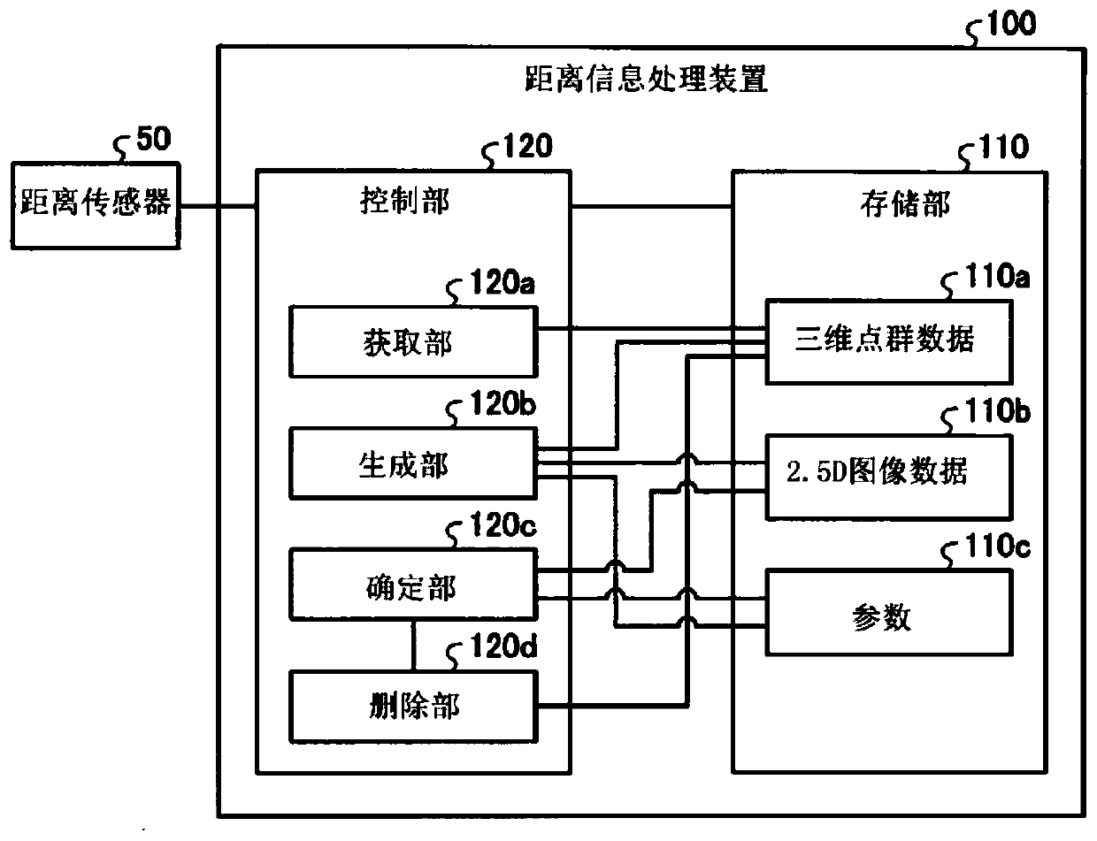
[0033] figure 1 is a functional block diagram showing the configuration of the distance information processing device according to the present embodiment. Such as figure 1 As shown, the distance information processing device 100 is connected to a distance sensor 50 . The distance sensor 50 outputs three-dimensional point cloud data representing the three-dimensional coordinates of each point on the three-dimensional object to the distance information processing device 100 .

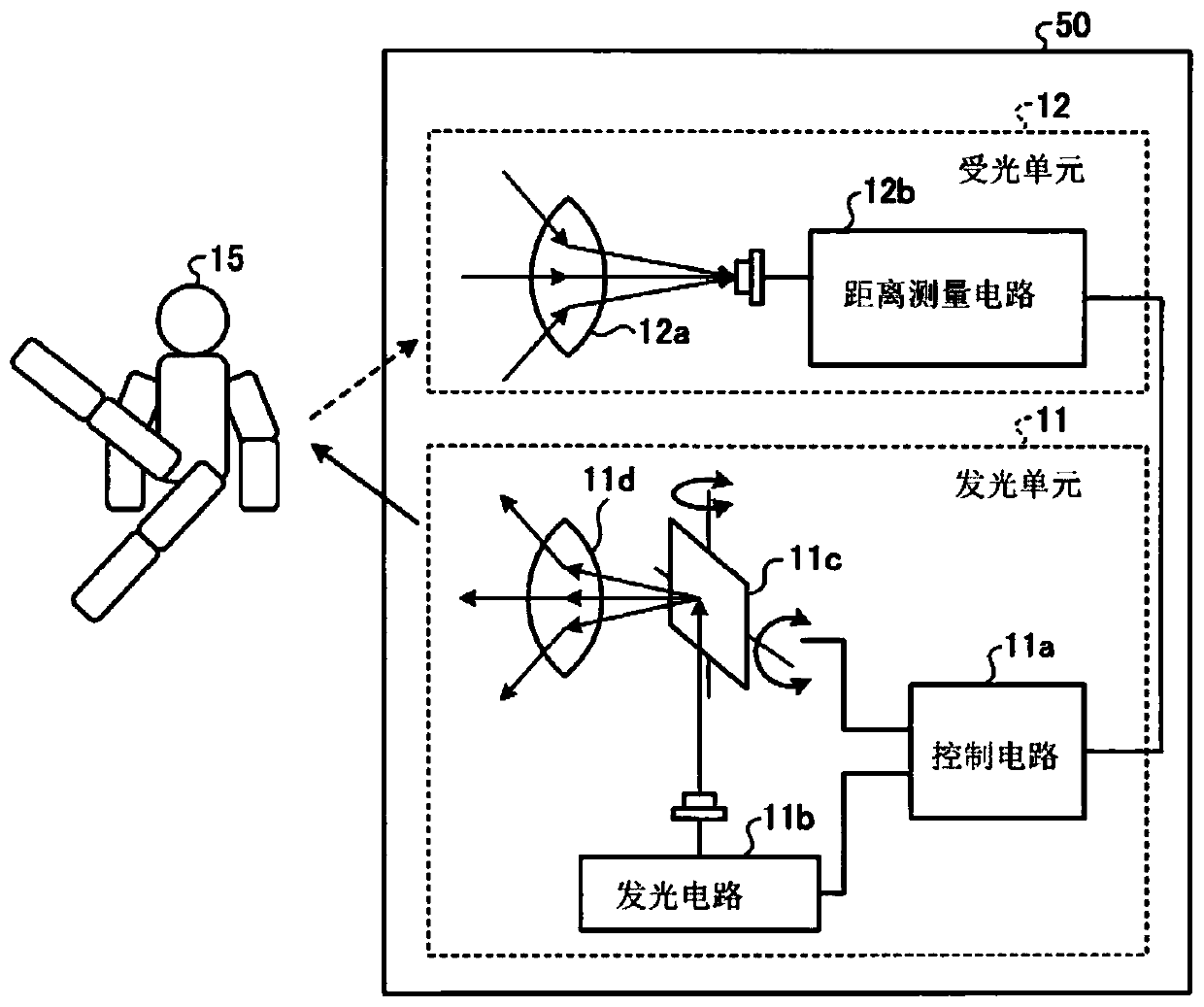
[0034] figure 2 It is a figure which shows an example of a distance sensor. The distance sensor 50 has a light emitting unit 11 and a light receiving unit 12 . The light emitting unit 11 is a device that emits laser light on the three-dimensional object 15 . The light receiving unit 12 is a device that receives laser light reflected from the three-dimensional object 15 .

[0035] The light emitting unit 11 has a control circuit 11a, a light emitting circuit 11b, a reflector 11c, and a lens 11d. ...


PUM


Abstract

A distance information processing device (100) generates, on the basis of three-dimensional point cloud data indicating the three dimensional coordinates of each point on a three-dimensional object, image data associating the two-dimensional coordinates of each point with the depth of each point. The distance information processing device (100) specifies, as points of interest, points in the three-dimensional point cloud data corresponding to contour pixels included in a contour part of the image data and specifies, as surrounding points, points in the three-dimensional point cloud data corresponding to pixels surrounding the contour pixels. The distance information processing device (100) deletes a point of interest on the basis of the number of surrounding points that are less than a prescribed distance from the point of interest.

Description

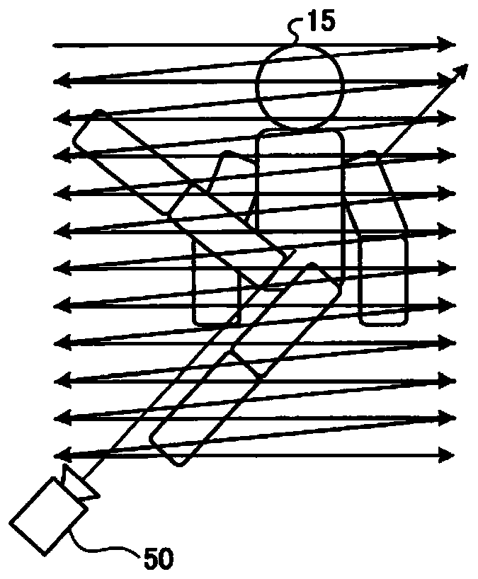
technical field [0001] The present invention relates to a distance information processing device and the like. Background technique [0002] When the shape of a three-dimensional object is measured using a distance sensor, edge noise may occur in the depth direction of the outline of the three-dimensional object compared to the actual position. Figure 15 as well as Figure 16 is a diagram for explaining edge noise. Such as Figure 15 As shown, if the distance sensor 10 is used to measure the three-dimensional object 15, then Figure 16 The three-dimensional point group data 20 shown. exist Figure 16 In the example shown, in the three-dimensional point cloud data, each point 21 becomes edge noise. [0003] An example of conventional techniques for removing edge noise will be described. Figure 17 It is a figure for explaining an example of the prior art. In the prior art, the point cloud density is calculated by calculating the distance from each point included in the...

Claims


Application Information

Patent Timeline
Patent Type & Authority Applications(China)
IPC IPC(8): G01B21/00G01B11/00
CPCG01B11/00G01B21/00G06T2207/10028G06T5/70G06T7/521G06T7/73G06T7/13
Inventor 吉村和浩
Owner FUJITSU LTD
Learn More