Outdoor rainproof power meter cabinet

A technology for power meters and meters, which is applied to electrical components, substation/distribution device shells, substation/switch layout details, etc., can solve problems affecting the normal operation of power meters, achieve the effect of easy disassembly and assembly, and enhance the heat dissipation effect

Active Publication Date: 2019-11-19
山东一开电气设备有限公司
View PDF7 Cites 0 Cited by
  • Summary
  • Abstract
  • Description
  • Claims
  • Application Information

AI Technical Summary

Problems solved by technology

Moreover, in order to dissipate heat, some outdoor power meter cabinets in the prior art usually have cooling holes on the side wall of the cabinet body. When it rains, rainwater easily enters the power meter cabinet from the cooling holes, affecting the normal operation of the power meter.

Method used


Image

  • Outdoor rainproof power meter cabinet
  • Outdoor rainproof power meter cabinet
  • Outdoor rainproof power meter cabinet

Examples


Embodiment 1

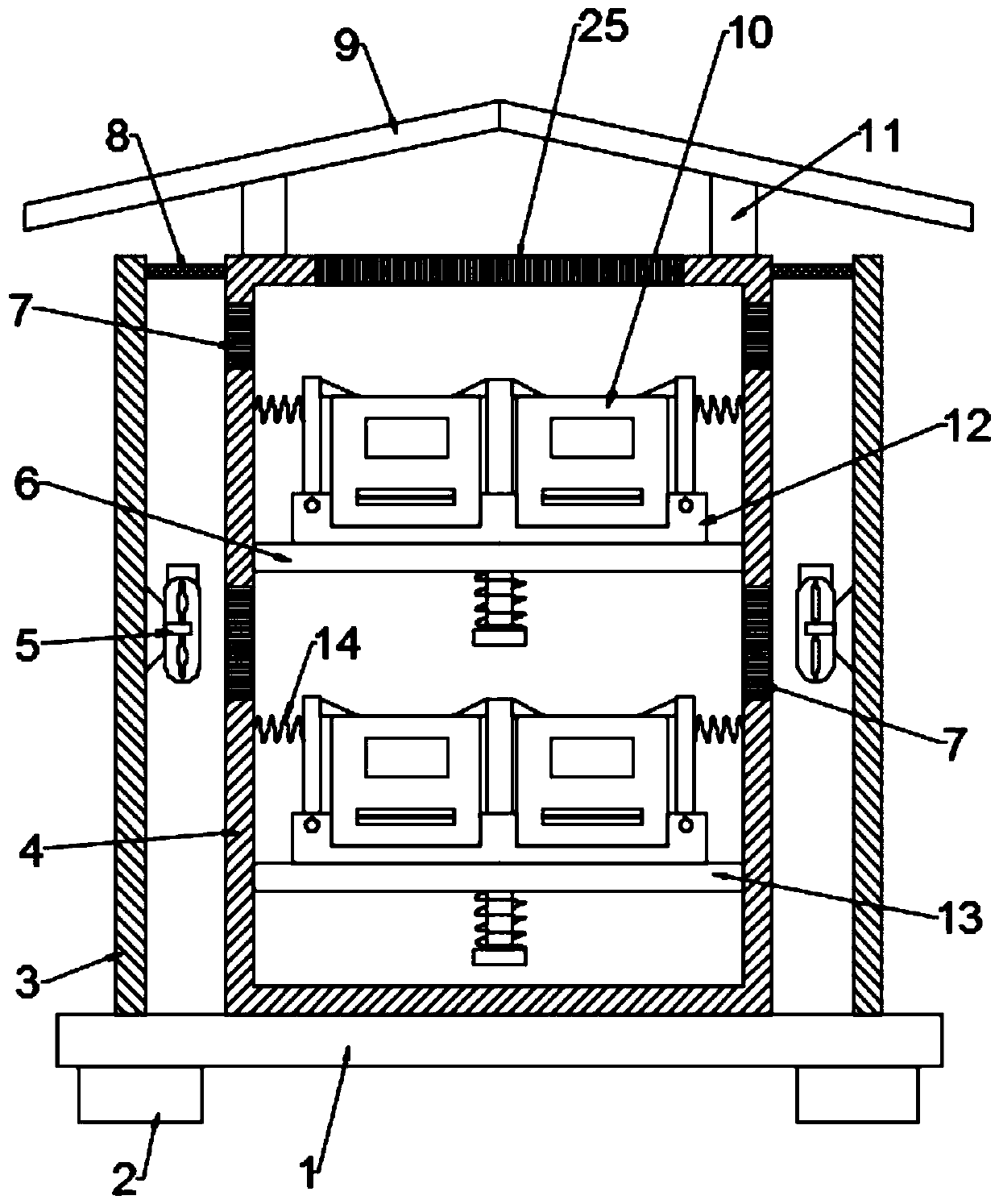
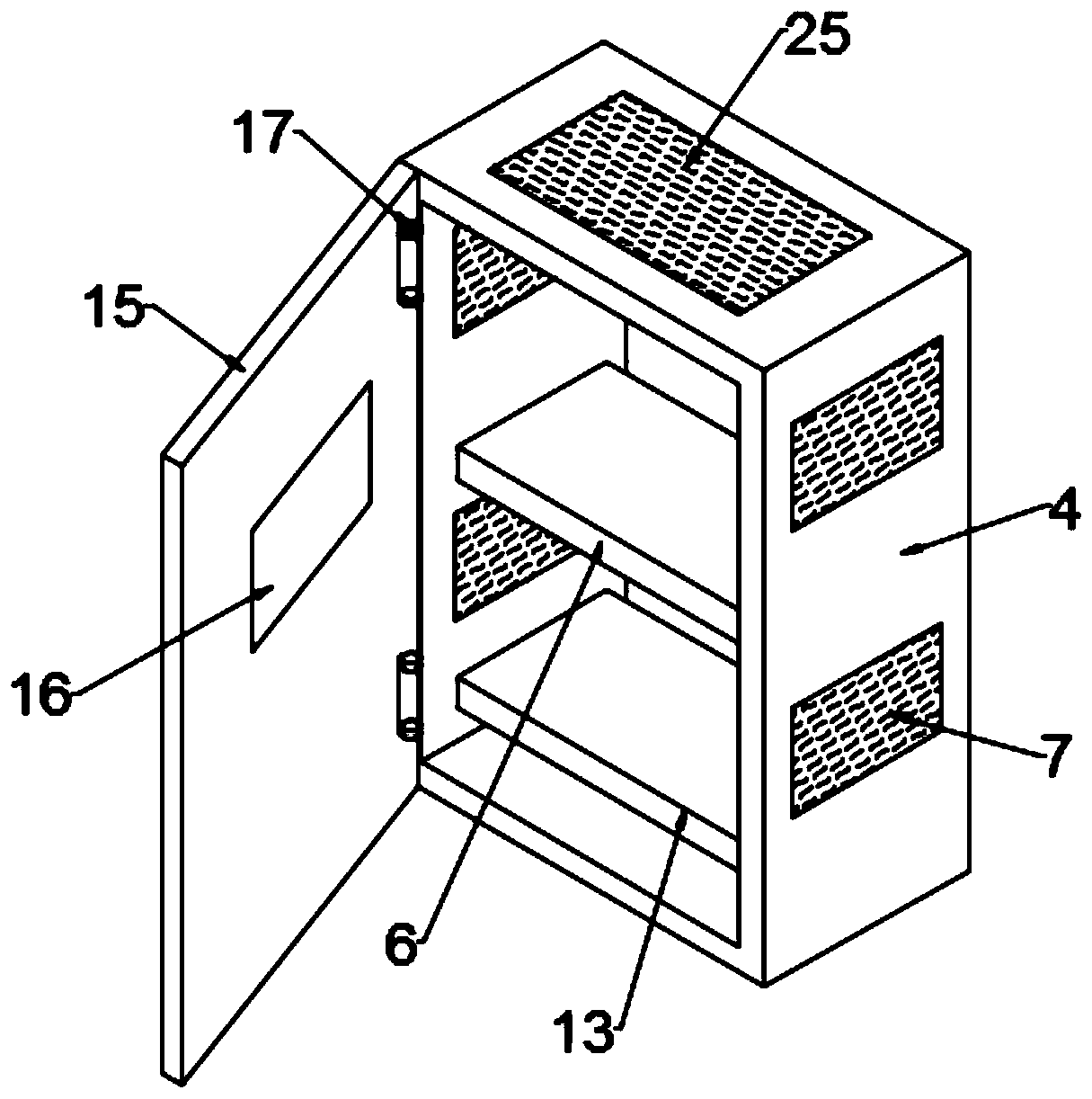
[0028] See Figure 1-4 In the embodiment of the present invention, an outdoor rainproof power meter cabinet includes a base 1, a support leg 2 is provided at the bottom of the base 1, a cabinet 4 is installed on the base 1, and the front side of the cabinet 4 is hinged by a hinge 17. There is a cabinet door 15 with a glass window 16 on the cabinet door 15; a first mounting plate 6 and a second mounting plate 13 are provided in the cabinet body 4, and the first mounting plate 6 and the second mounting plate 13 are provided with Install the meter seat 12 of the power meter 10, and the meter seat 12 is provided with a fixing mechanism for fixing the power meter 10; place the power meter 10 on the meter seat 12, and then fix it by the fixing mechanism to complete the installation, which is easy to disassemble The effect of

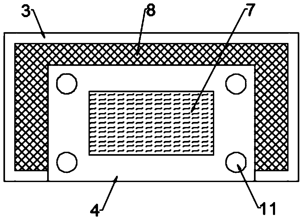
[0029] The side wall of the base 1 is provided with a first heat dissipation hole 7, and the left, right and rear sides of the base 1 are provided with outer ba...

Embodiment 2

[0040] See Figure 5 In the embodiment of the present invention, an outdoor rainproof power meter cabinet is different from the embodiment 1. The rainproof shed 9 is provided with a column 30, the top of the column 30 is provided with a bird repellent 26, and the column 30 is Rotation is provided with a collar 29, the outer side of the collar 29 is connected with a rotating rod 28, the end of the rotating rod 28 away from the collar 29 is provided with a moving blade 27; through the rotation of the collar 29 and the column 30, the moving blades 27 and The rotating rod 28 can be rotated, and the cooperation of the bird repelling thorns 26 can achieve the purpose of repelling birds, so that the outdoor rainproof power instrument cabinet has the function of repelling birds.


PUM


Abstract

The invention relates to the electric power equipment technology field and discloses an outdoor rainproof power meter cabinet. The cabinet comprises a pedestal. A cabinet body is installed on the pedestal. A first installation plate and a second installation plate are arranged in the cabinet body. The first installation plate and the second installation plate are provided with a meter seat for installing a power meter. The meter seat is provided with a fixing mechanism used for fixing a power meter. A side wall of the pedestal is provided with a first heat dissipation hole. Left and right sides and a rear side of the pedestal are provided with outer baffle plates. Bottoms of the outer baffle plates are installed on the pedestal. A support column is arranged on a top wall of the cabinet body, and a rainproof shed is installed on the support column. In the outdoor rainproof power meter cabinet, rainwater can be blocked through the rainproof shed and the outer baffle plates so as to prevent the rainwater from entering into the cabinet body from the first heat dissipation hole and affecting normal operation of the power meter. And simultaneously, a space between the outer baffle paltesand the cabinet body and the space between the rainproof shed and the cabinet body can form an airflow so that heat dissipation is not affected.

Description

Technical field [0001] The invention relates to the technical field of power equipment, in particular to an outdoor rainproof power meter cabinet. Background technique [0002] The power meter cabinet is used to install power meters. Some outdoor power meter cabinets need to be installed outdoors and are often corroded by rain. Moreover, in order to dissipate heat, some outdoor power meter cabinets in the prior art usually have heat dissipation holes on the side walls of the cabinet. When it rains, rainwater will easily enter the power meter cabinet from the heat dissipation holes and affect the normal operation of the power meters. In view of the above problems, the present invention proposes an outdoor rainproof power meter cabinet. Summary of the invention [0003] The purpose of the present invention is to provide an outdoor rainproof power meter cabinet to solve the above-mentioned background art problems. [0004] In order to achieve the above objectives, the present invent...

Claims


Application Information

Patent Timeline
IPC IPC(8): H02B1/56H02B1/28H02B1/30H02B1/32A01M29/32A01M29/06
CPCA01M29/06A01M29/32H02B1/28H02B1/30H02B1/32H02B1/565
Inventor 不公告发明人
Owner 山东一开电气设备有限公司
Why Eureka
Try Eureka