
Phased array beam control device and control method thereof

A technology of beam control and control method, which is applied in the field of phased array beam control devices, can solve problems such as heavy maintenance workload, increased computing time, and influence on beam scanning speed, and achieve the effect of reducing hardware cost and quantity

Active Publication Date: 2019-11-19
XTR SOLUTIONS
View PDF9 Cites 6 Cited by
  • Summary
  • Abstract
  • Description
  • Claims
  • Application Information

AI Technical Summary

Problems solved by technology

[0002] The beam control devices of phased array radar usually include centralized and distributed. Among them, centralized means that a set of beam control devices performs unified calculations on the amplitude and phase of each array unit of the phased array, and shifts the phase after the calculation is completed. The data of the attenuator and the attenuator are distributed to each antenna array unit, the amount of hardware equipment is small, and the cost is low, but the calculation time will increase with the increase of antenna units, which will affect the speed of beam scanning
Distributed means that the entire array antenna is divided into multiple sub-arrays, each sub-array is controlled by a beam control device, and each beam control device only calculates the phase shift amount of the RF transmitting and receiving components in this sub-array, thereby reducing the calculation time and satisfying the requirements of beam control. However, the increase in the number of beam control devices required will increase the cost, decrease the reliability, and increase the workload of debugging and maintenance.

Method used


Image

  • Phased array beam control device and control method thereof
  • Phased array beam control device and control method thereof
  • Phased array beam control device and control method thereof

Examples


Embodiment Construction

[0061] This section will describe the specific embodiments of the present invention in detail. The preferred embodiments of the present invention are shown in the accompanying drawings. The function of the accompanying drawings is to supplement the description of the text part of the manual with graphics, so that people can intuitively and vividly understand this Each technical feature and overall technical solution of the invention cannot be understood as a limitation on the protection scope of the present invention.

[0062] In the description of the present invention, it should be understood that the orientation description involved, such as up, down, front, back, left, right, etc., indicates the orientation or positional relationship based on the orientation or positional relationship shown in the drawings, and only In order to facilitate the description of the present invention and simplify the description, it does not indicate or imply that the pointed device or element must...


PUM


Abstract

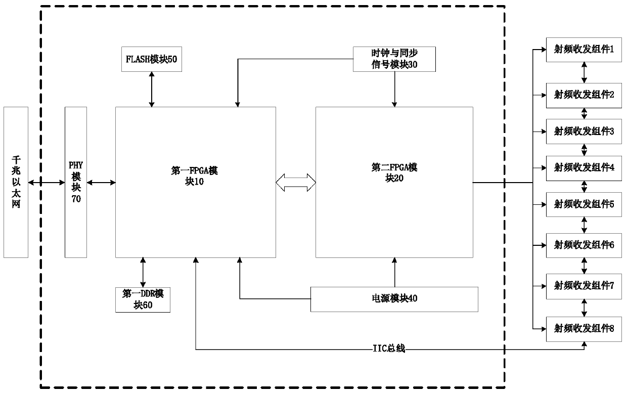
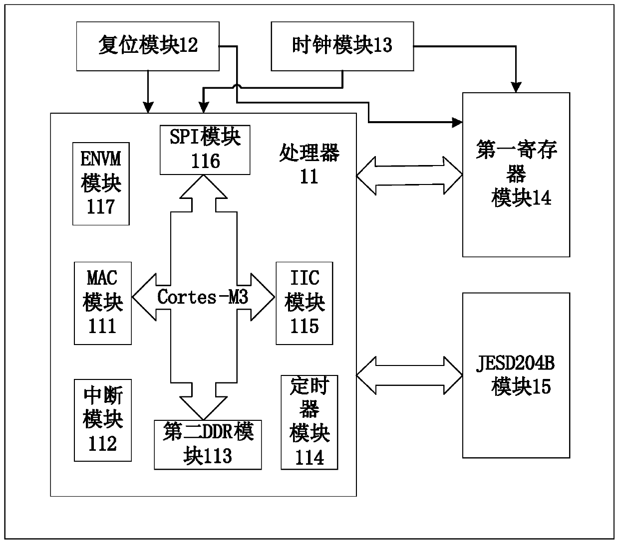
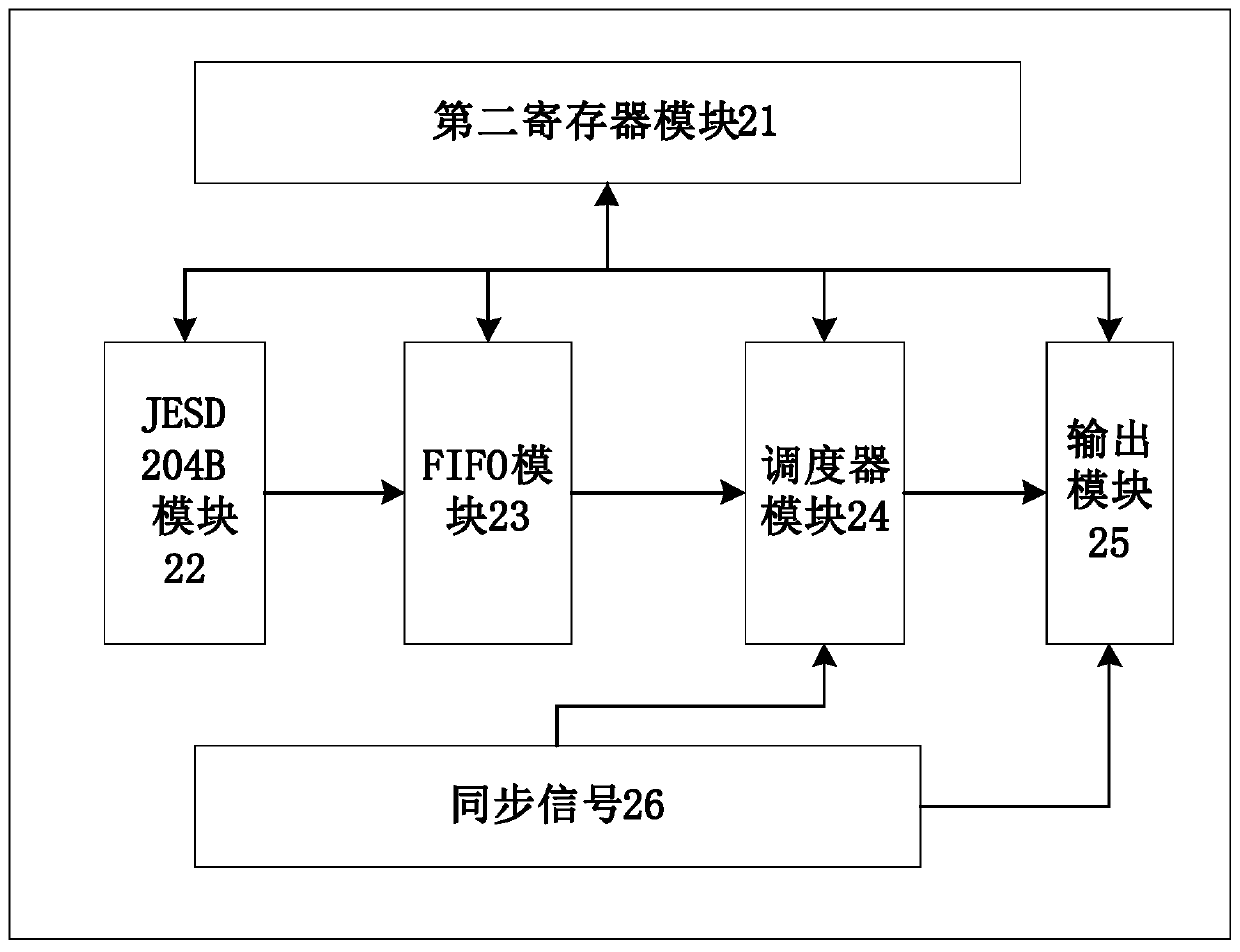
The invention discloses a phased array beam control device, a firmware upgrading method and radar. The phased array beam control device comprises: a first FPGA module used for the real-time processingof phase data of a beam; a second FPGA module used for outputting corresponding instructions to a plurality of radio frequency transceiving components according to the data processed by the first FPGA module; a clock and synchronizing signal module used for generating a clock signal and synchronizing the clock signal to the first FPGA module and the second FPGA module; a first DDR module used forstoring the process data generated by the first FPGA module; an FLASH module used for storing configuration information required by loading; and a power supply module used for supplying power to thefirst FPGA module and the second FPGA module. According to the single phased array beam control device composed of the first FPGA module and the second FPGA module, logic control for the plurality ofradio frequency transceiving components can be achieved at the same time, the number of beam control devices is reduced, and therefore, the hardware cost of the system is reduced.

Description

Technical field [0001] The invention relates to the technical field of signal processing, in particular to a phased array beam control device and a control method thereof. Background technique [0002] The beam control devices of phased array radar usually include centralized and distributed. Among them, centralized refers to the unified operation of the amplitude and phase of each array unit of the phased array by a set of beam control devices. After the calculation is completed, the phase will be shifted. The data of the receiver and the attenuator is distributed to each antenna array unit, the amount of hardware equipment is small, and the cost is low, but the computing time will increase with the increase of the antenna unit, which affects the speed of beam scanning. Distributed means that the entire array antenna is divided into multiple sub-arrays. Each sub-array is controlled by a beam control device. Each beam control device only calculates the phase shift of the radio fr...

Claims


Application Information

Patent Timeline
Patent Type & Authority Applications(China)
IPC IPC(8): G05B19/042G01S7/02G01S13/02
CPCG01S7/02G01S13/02G01S2013/0245G05B19/0423G05B2219/25257
Inventor 包晓军刘远曦李琳刘会涛王育才刘航黄辉
Owner XTR SOLUTIONS
Learn More