an optical module

An optical module and laser technology, applied in the field of optical modules, can solve the problems affecting the optical coupling effect, etc., to achieve the effect of ensuring the optical coupling effect, reducing the impact, and reducing the return loss of received light

Active Publication Date: 2021-11-05
HISENSE BROADBAND MULTIMEDIA TECH
View PDF5 Cites 0 Cited by
  • Summary
  • Abstract
  • Description
  • Claims
  • Application Information

AI Technical Summary

Problems solved by technology

[0005] The invention provides an optical module to solve the problem that the existing optical module is prone to produce optical return loss and affect the optical coupling effect

Method used


Image

  • an optical module
  • an optical module
  • an optical module

Examples


Embodiment Construction

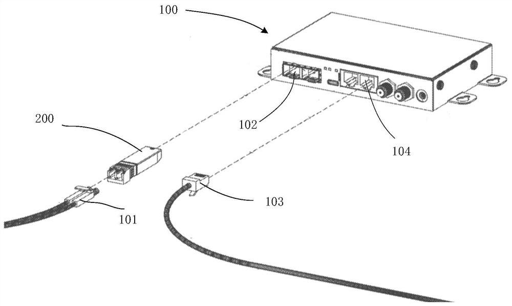
[0033] One of the core links of optical fiber communication is the conversion of photoelectric signals. Optical fiber communication uses optical signals carrying information to be transmitted in optical fibers / optical waveguides, and low-cost, low-loss information transmission can be achieved by using the passive transmission characteristics of light in optical fibers. However, information processing equipment such as computers use electrical signals, which requires mutual conversion between electrical signals and optical signals during signal transmission.

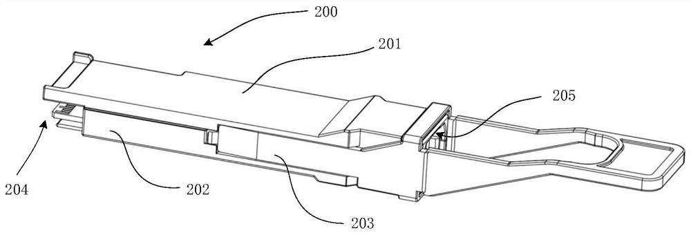
[0034] The optical module realizes the above-mentioned photoelectric conversion function in the field of optical fiber communication technology, and the mutual conversion between optical signals and electrical signals is the core function of the optical module. The optical module realizes the electrical connection with the external host computer through the gold finger on the circuit board. The main electrical connection ...


PUM


Abstract

The invention discloses an optical module, comprising a casing and an optical fiber adapter located at one end of the casing. The casing includes a laser chip, a first filter, a reflection plate, a second filter, a reflection prism assembly and a light receiving chip. The optical signal emitted by the laser chip enters the optical fiber adapter through the first filter and then exits; the optical signal from the optical fiber adapter is reflected by the first filter and the reflection sheet and then passes through the second filter to the reflection prism assembly; the input of the reflection prism assembly The light surface and the propagation direction of the optical signal are at a non-perpendicular angle. The non-vertical angle can reduce the return loss of the received light. The end face of the reflective prism assembly is an inclined reflective slope. The optical signal propagates to the reflective slope and is reflected to the light-emitting bottom surface. It is received by the light receiving chip under the bottom surface of the light output. It can be seen that, in the optical module provided by the present invention, the light incident surface of the reflective prism assembly is inclined, which can reduce the return loss of the received light, thereby reducing the influence on the optical signal transmission, and ensuring the optical coupling effect.

Description

technical field [0001] The invention relates to the technical field of optical fiber communication, in particular to an optical module. Background technique [0002] Due to the increasingly high requirements for communication bandwidth in the field of optical fiber communication, the global optical communication is in a period of rapid development. In the field of high-speed data communication, in order to ensure long-distance high-speed transmission of data, optical modules are usually used in this field to realize the transmission and reception of light of different wavelengths. [0003] Existing optical modules generally refer to integrated modules for photoelectric conversion, which are respectively equipped with corresponding optical fiber adapters for the light emitting device and the light receiving device to form a coaxially packaged optical module. However, due to the large volume of the optical fiber adapter, the optical module is adapted to two optical fiber adap...

Claims


Application Information

Patent Timeline
Patent Type & Authority Patents(China)
IPC IPC(8): G02B6/42
CPCG02B6/4204G02B6/4206G02B6/4208G02B6/4214G02B6/4215G02B6/4244
Inventor 葛建平傅钦豪黄绪杰谢一帆
Owner HISENSE BROADBAND MULTIMEDIA TECH
Why Eureka
Try Eureka