Biomass steam generator
A steam generator and biomass technology, applied in steam generation, steam boilers, combustion methods, etc., can solve the problems of large space occupation, low combustion efficiency, and complex structure, so as to improve heat exchange efficiency, increase heat exchange path, The effect of taking up little space
- Summary
- Abstract
- Description
- Claims
- Application Information
AI Technical Summary
Problems solved by technology
Method used
Image

Examples
Embodiment 1
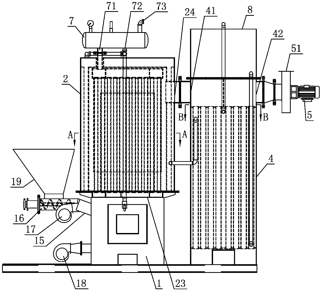
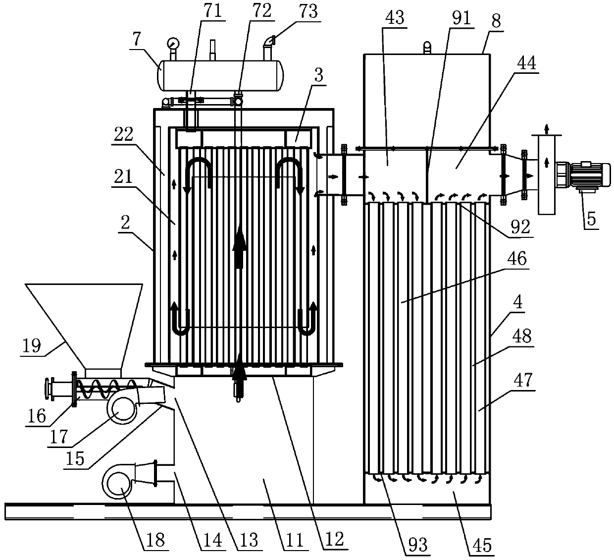
[0027] Such as figure 1 and figure 2 As shown, a biomass steam generator described in this embodiment includes: a combustion chamber 1 with a furnace cavity 11 , a steam chamber 2 with a first sealed cavity 21 and a heat exchanger 4 . On the top of the combustion chamber 1, there is a total flue gas outlet 12 connected with the furnace chamber 11, and on the side wall of the combustion chamber 1, there are respectively provided with a feed port 13 and an air supplement port 14 connected with the furnace chamber 11, and the feed port 13 Located on the upper side wall of the combustion chamber 1 , the air supplement port 14 is located on the side wall of the combustion chamber 1 below the feed inlet 13 . Feed pipe 15 is provided at feed inlet 13 places, and the output port of screw conveyor 16 and the air outlet of first blower fan 17 are all connected with feed inlet 13 by feed pipe 15, and the feeding of screw conveyor 16 A feed hopper 19 is also provided at the mouth. In ...
Embodiment 2
[0045] The difference between this embodiment and Embodiment 1 is that this embodiment also adds a water jacket interlayer on the basis of Embodiment 1, specifically:
[0046] Such as Figure 7 As shown, the steam chamber 2 includes an inner cavity wall and an outer cavity wall, and a water jacket interlayer 22 is formed between the inner cavity wall and the outer cavity wall. An interlayer water inlet 25 and an interlayer water outlet 26 communicating with the water jacket interlayer 22 are respectively provided on the outer cavity wall of the steam chamber 2, and the water outlet 40 of the heat exchanger 4 is connected with the interlayer water inlet 25 through a connecting pipe 64, The interlayer water outlet 26 communicates with the sealed rectangular cavity of the lower box body 34 through the water inlet pipe 66 , the water pump 67 and the water outlet pipe 68 .
[0047] The water tank 8 communicates with the water inlet 49 of the heat exchanger 4 through the water tank...
Embodiment 3
[0053] The difference between this embodiment and Embodiment 1 or Embodiment 2 is that the specific structure of the heat exchanger 4 is set, specifically:
[0054] Such as figure 2 and Figure 6 As shown, the heat exchanger 4 is a shell with a second sealed cavity, and a first partition plate 92 and a second partition plate 93 are arranged at intervals from top to bottom in the second sealed cavity. A partition plate 92 and a second partition plate 93 divide the second sealed cavity into three separate upper, middle and lower cavities: the upper cavity, the middle cavity 48 and the lower cavity 45 . A third partition plate 91 is vertically arranged in the middle of the upper cavity, and the third partition plate 91 divides the upper cavity into two independent cavities: the first cavity 43 and the second cavity 44 . The second flue gas inlet 41 of the heat exchanger 4 communicates with the first cavity 43 , and the second flue gas outlet 42 of the heat exchanger 4 communic...
PUM
 Abstract
Description
Claims
Application Information
 - R&D
- Intellectual Property
- Life Sciences
- Materials
- Tech Scout
- Unparalleled Data Quality
- Higher Quality Content
- 60% Fewer Hallucinations
Browse by: Latest US Patents, China's latest patents, Technical Efficacy Thesaurus, Application Domain, Technology Topic, Popular Technical Reports.
© 2025 PatSnap. All rights reserved.Legal|Privacy policy|Modern Slavery Act Transparency Statement|Sitemap|About US| Contact US: help@patsnap.com