
Tailstock type tilting rotor vertical takeoff and landing unmanned aerial vehicle

A tilt-rotor, vertical take-off and landing technology, applied to vertical take-off and landing aircraft, rotorcraft, motor vehicles, etc., can solve the problems of adding redundant power, instability, and prone to vibration of attitude, so as to simplify the structure and improve reliability sexual effect

Inactive Publication Date: 2019-11-19
XI AN JIAOTONG UNIV
View PDF17 Cites 2 Cited by
  • Summary
  • Abstract
  • Description
  • Claims
  • Application Information

AI Technical Summary

Problems solved by technology

[0004] Although the tailseat vertical take-off and landing UAV combines the advantages of the mixed-wing vertical take-off and landing UAV and the tilt-rotor vertical take-off and landing UAV, its maneuverability is affected by the uniqueness of its vertical take-off and landing method.
Especially when the area of ​​the wing is large, the landing is easily affected by the crosswind, and the attitude is prone to shock and even instability
Although the current tail seat UAV [patent CN 108639328 A] and patent [CN 106184738 B] with cross-symmetrically distributed wings can weaken the disadvantages of this fuselage structure, but at the expense of the structural simplicity of the whole machine At the expense of the flexibility of the fuselage, redundant power has to be added, which also brings other risks

Method used


Image

  • Tailstock type tilting rotor vertical takeoff and landing unmanned aerial vehicle
  • Tailstock type tilting rotor vertical takeoff and landing unmanned aerial vehicle
  • Tailstock type tilting rotor vertical takeoff and landing unmanned aerial vehicle

Examples


Embodiment Construction

[0028] The present invention will be described in further detail below in conjunction with the accompanying drawings.

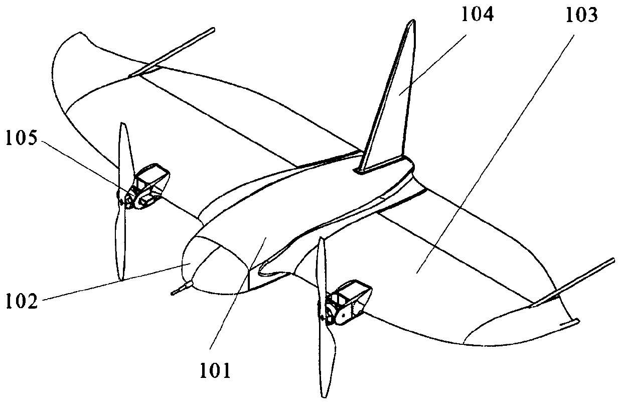
[0029] Such as figure 1 As shown, the tailseat tiltrotor vertical take-off and landing UAV of the present invention includes a fuselage assembly 101 , a nose cover assembly 102 , a wing assembly 103 , an empennage 104 , and a tiltrotor power mechanism 105 . The wing assembly 103 is symmetrically distributed left and right relative to the fuselage, and the tilt rotor power mechanism 105 is installed on the leading edge of the wing assembly 103 . The empennage 104 is perpendicular to the fuselage assembly 101 .

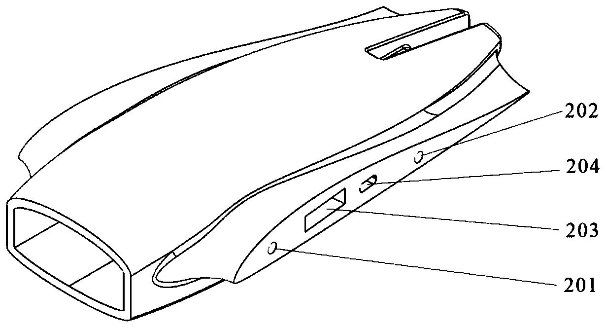
[0030] Such as figure 2 As shown in the fuselage assembly 101 , a first positioning hole 201 , a second positioning hole 202 , a square reinforcing tube hole 203 and an electrical interface A204 are provided at the end surface connected to the wing assembly 103 .

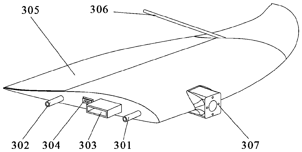
[0031] Such as image 3 The front side of the wing assembly 103 is shown, and the c...


PUM


Abstract

The invention provides a tailstock type tilting rotor vertical takeoff and landing unmanned aerial vehicle. The tailstock type tilting rotor vertical takeoff and landing unmanned aerial vehicle comprises a vehicle body assembly. The left and right sides of the vehicle body assembly are symmetrically provided with wings. The front end of the vehicle body assembly is provided with a bow cap assembly. The front edge of each wing assembly is provided with a tilting rotor power mechanism. The rear portion of the vehicle body assembly is provided with a tail wing. The tail wing is arranged perpendicular to the vehicle body assembly. The flexibility of the unmanned aerial vehicle is improved through the tilting rotor power mechanisms. Forward momentum for vertical takeoff and landing and level flight is provided for the unmanned aerial vehicle. Air resistance during flight is reduced through flying wing configuration. Yawing of the unmanned aerial vehicle is controlled through the speed differential of left and right propellers. The structure of the unmanned aerial vehicle is simplified in an aileron and elevating rudder combined mode. The tailstock type tilting rotor vertical takeoff andlanding unmanned aerial vehicle has the characteristics of being high in flexibility, good in maneuverability, small in cruise resistance and high in reliability.

Description

technical field [0001] The invention relates to the technical field of aircraft structure design, in particular to a tail seat type tilt rotor vertical take-off and landing unmanned aerial vehicle. Background technique [0002] At present, the development of UAVs is in full swing, and the types and uses of UAVs are becoming more and more diverse. Among them, the vertical take-off and landing fixed-wing UAVs are gradually favored by researchers and users due to their long battery life, large load, and vertical take-off and landing. favorite. Due to its unique take-off and landing method, the vertical take-off and landing UAV can complete fixed-point take-off and landing without a runway, and also has a hovering function. [0003] Vertical take-off and landing UAVs are roughly divided into three categories, one is mixed-wing vertical take-off and landing UAVs, the other is tilt-rotor vertical take-off and landing UAVs, and the other is tailseat vertical take-off and landing U...

Claims


Application Information

Patent Timeline
IPC IPC(8): B64C29/00B64C27/22B64C27/12B64C5/06
CPCB64C5/06B64C27/12B64C27/22B64C29/00
Inventor 高忠权韩鲁冰高僖黄佐华
Owner XI AN JIAOTONG UNIV
Learn More