
Mold frame system capable of quickly replacing mold core

A mold base and mold core technology, which is applied in the field of mold base systems for rapid mold core replacement, can solve problems such as low efficiency, and achieve the effects of convenient mold change operation, high mold change efficiency, and rapid line change production.

Pending Publication Date: 2019-11-19
中山英诺莱比智能科技有限公司
View PDF0 Cites 4 Cited by
  • Summary
  • Abstract
  • Description
  • Claims
  • Application Information

AI Technical Summary

Problems solved by technology

[0004] The purpose of the present invention is to provide a mold base system that can quickly replace the mold core, so as to solve the technical problem of low efficiency caused by the need to disassemble the mold from the injection molding machine to replace the mold core during line change production in the prior art

Method used


Image

  • Mold frame system capable of quickly replacing mold core
  • Mold frame system capable of quickly replacing mold core
  • Mold frame system capable of quickly replacing mold core

Examples


Embodiment 1

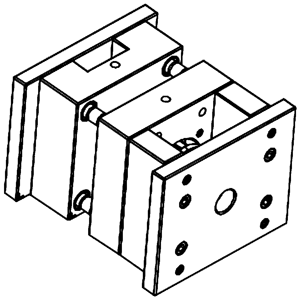
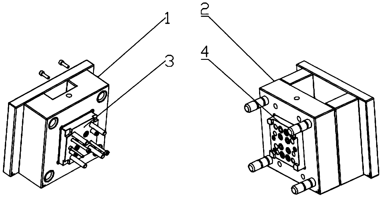
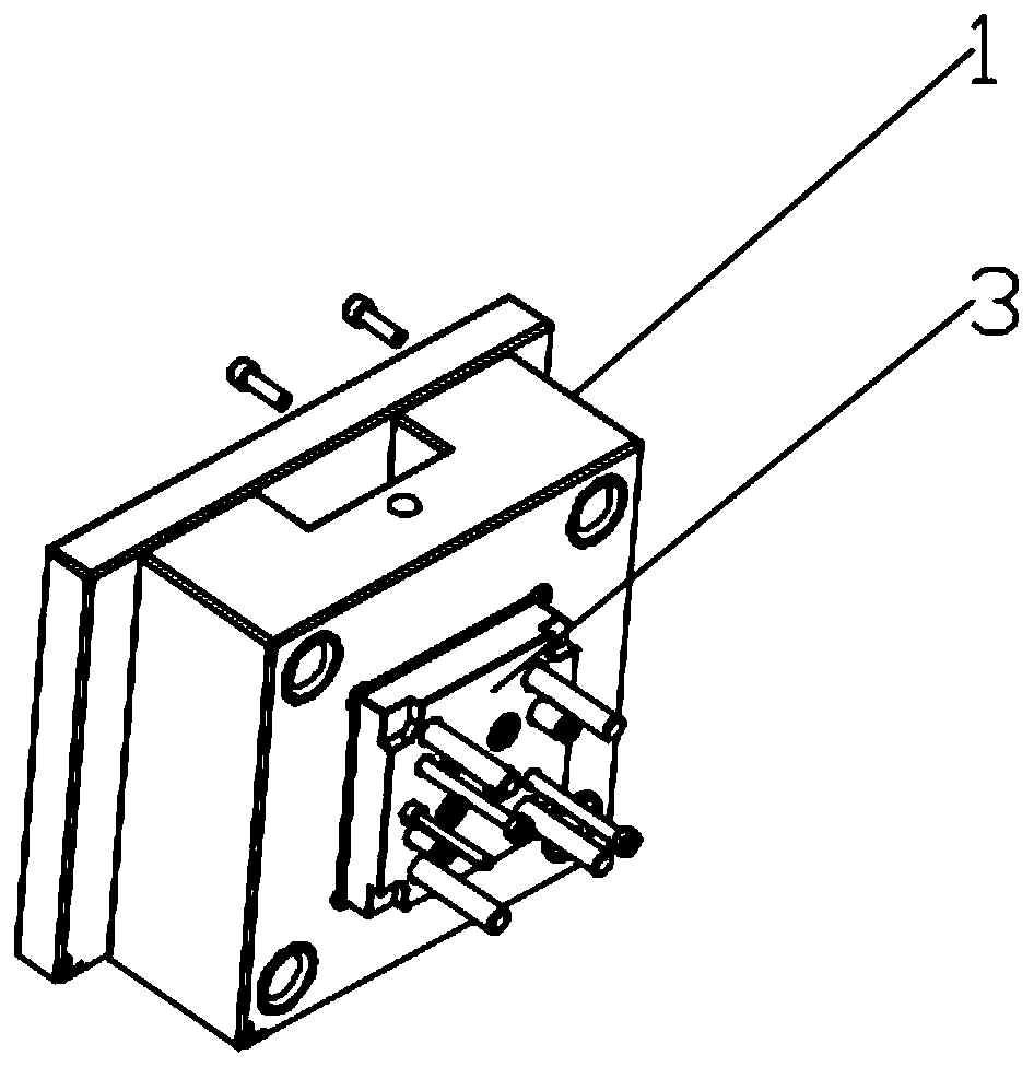
[0053] The mold base system that can quickly replace the mold core provided by the present invention includes a front mold base 1, a rear mold base 2, a front mold core 3 and a rear mold core 4, wherein,

[0054] The front mold core 3 and the rear mold core 4 are respectively connected to each other by the front mold base 1 and the rear mold base 2 so that the front mold core 3 and the rear mold core 4 are joined to the joint surface. Mold closing, after the front mold core 3 and the rear mold core 4 are mold closed, the mold cavity arranged on the front mold core 3 and / or the rear mold core 4 is formed as a complete injection molding cavity;

[0055] The front mold base 1 and the rear mold base 2 are all provided with mold core installation grooves, which are respectively the front mold core installation groove 11 and the rear mold core installation groove 21,

[0056] The front mold core 3 and the rear mold core 4 are respectively arranged in the mold core installation groov...

Embodiment 2

[0065] The difference between this embodiment 2 and embodiment 1 is that the mold core installation groove is a one-side through structure, and both sides of the front mold core 3 and the rear mold core 4 are provided with snap-in grooves 32, The position direction of the clamping groove 32 on the front mold core 3 and the rear mold core 4 is consistent with the direction of the mold core installation groove, and the clamping block 61 of the clamping member 6 can be inserted into the clamping groove to The positions of the front mold core 3 and the rear mold core 4 are defined, and the clamping member 6 can be fixed on the front mold frame 1 and the rear mold frame 2 by bolts.

Embodiment 3

[0066] Embodiment 3: The difference between this embodiment 3 and embodiment 2 is that: the front core 3 and the rear core 4 are both trapezoidal structures with a small top and a wide bottom, and the mounting grooves of the cores are all in line with the The front mold core 3 and the rear mold core 4 can match the trapezoidal structure, and the front mold core 3 and the rear mold core 4 can slide in the mold core installation groove.


PUM


Abstract

The invention provides a mold frame system capable of quickly replacing a mold core, and relates to the technical field of molds. The mold frame system capable of quickly replacing the mold core solves the technical problem of low efficiency caused by the fact that the mold core can be replaced only when the mold is disassembled from an injection molding machine during wire changing production inthe prior art. The mold frame system capable of quickly replacing the mold core comprises a front mold frame, a rear mold frame, a front mold core and a rear mold core, wherein mold core mounting grooves are formed in the front mold frame and the rear mold frame, the front mold core and the rear mold core are correspondingly arranged in the mold core mounting grooves of the front mold frame and the rear mold frame, threaded holes are formed in the back surfaces, opposite to a mold clamping surface, of the front mold core and the rear mold core, bolts can correspondingly penetrate through the mold core mounting grooves of the front mold frame and the rear mold frame and can be correspondingly connected with corresponding threaded holes in a threaded way, and the front mold core, and the rear mold core and the rear mold frame can be matched with the threaded holes through bolts. According to the mold frame system capable of quickly replacing a mold core, the mold replacing efficiency isvery high and rapid line changing production is realized.

Description

technical field [0001] The invention relates to the technical field of moulds, in particular to a mold base system capable of quickly replacing mold cores. Background technique [0002] According to the production quantity, injection molding products can be divided into two types: mass production and small batch production. Small batch production is characterized by small quantity and extremely short delivery time, so molds cannot be molded into one product like traditional molds. Most of the current market models are one mold base with multiple sets of mold cores, that is, one mold base with multiple molds Core products. However, this mode still has troublesome problems in the injection molding process. When changing the mold core for production, the entire mold needs to be removed from the injection molding machine, loaded and unloaded, and then installed on the injection molding machine. This takes at least one hour. Injection molding The machine is also in an invalid s...

Claims


Application Information

Patent Timeline
Patent Type & Authority Applications(China)
IPC IPC(8): B29C45/26B29C45/40B29C33/30
CPCB29C45/2602B29C45/4005B29C33/306
Inventor 韦雪凯黄泳华
Owner 中山英诺莱比智能科技有限公司
Learn More