
Fiber core cutting and assembly device of fiber wiring terminal

A technology for connecting terminals and assembling devices, which is applied to the coupling of optical waveguides, light guides, optics, etc., can solve the problems of optical fiber flatness and end surface finish being difficult to guarantee, and achieves less physical damage, improved assembly success rate, and improved straightness. Effect

Active Publication Date: 2019-11-15
ZGT OPTICAL COMM LTD
View PDF4 Cites 0 Cited by
  • Summary
  • Abstract
  • Description
  • Claims
  • Application Information

AI Technical Summary

Problems solved by technology

This patent directly assembles the handle ferrule, and it is difficult to guarantee the flatness and end surface finish of the optical fiber

Method used


Image

  • Fiber core cutting and assembly device of fiber wiring terminal
  • Fiber core cutting and assembly device of fiber wiring terminal

Examples


Embodiment Construction

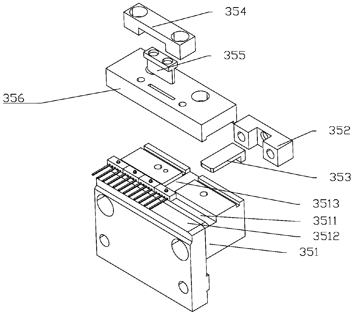
[0016] Such as figure 1 As shown, an optical fiber core cutting and assembly device for an optical fiber terminal includes a frame and a base 31 mounted on the frame, an optical fiber core feeding assembly 32, a first removal mechanism 33, a second removal mechanism 34, a transition The chute assembly 35, the third removal mechanism 36, the fourth removal mechanism 37, the pushing mechanism 38, the cutting mechanism 39 and the collection box 310; the base 31 is fixedly arranged on the frame, and the panel of the base 31 has holes , the base 31 is provided with a collection box 310; the optical fiber core feeding assembly 32 is located on the side of the base 31 and is connected with the first removal mechanism 33, the first removal mechanism 33 is installed on the base 31, and the second removal mechanism 33 The taking mechanism 34 is orthogonal to the first taking mechanism 33, the third taking mechanism 36 is connected with the transition chute assembly 35, the transition ch...


PUM


Abstract

The invention relates to a fiber core cutting and assembly device of a fiber wiring terminal. The device comprises a rack and a base, a fiber core loading assembly, a first moving and taking mechanism, a second moving and taking mechanism, a transition sliding groove assembly, a third moving and taking mechanism, a fourth moving and taking mechanism, a push mechanism, a cutting mechanism and a collection box which are arranged on the rack, wherein a hole is formed in a panel of the base, the collection box is arranged in the base, the fiber core loading assembly is arranged at a side of the base and is in linkage with the first moving and taking mechanism, the first moving and taking mechanism is arranged on the base, the second moving and taking mechanism is orthogonal to the first movingand taking mechanism, the third moving and taking mechanism is in linkage with the transition sliding groove assembly, the transition sliding groove assembly is arranged on the base, the transition sliding groove assembly and the third moving and taking mechanism are arranged orthogonally, and the cutting mechanism is arranged on the base and is arranged right above the transition sliding grooveassembly. The device is used for cutting and pressing a fiber core, a fiber is straight and is smooth in end part, and the light guide efficiency of the fiber is high.

Description

technical field [0001] The invention relates to the technical field of optical fiber device production, in particular to an optical fiber core cutting and assembling device for an optical fiber terminal. Background technique [0002] Generally, fiber optic connectors use plastic terminals and pins, which are mainly used in consumer electronics products such as video and audio or in short-distance optical fiber communications using plastic optical fibers. When users connect such consumer electronics products to After the power supply, the transmission of optical fiber signals is achieved by fitting the optical fiber terminal with the female seat of the optical fiber connector. Most of the commonly used optical fiber terminals are made of non-light-conducting plastic housings, and optical fibers are installed in the housings. The signal transmission has been realized by the docking between the optical fibers, and the signal transmission quality is related to the quality of the...

Claims


Application Information

Patent Timeline
Patent Type & Authority Applications(China)
IPC IPC(8): G02B6/38G02B6/25
CPCG02B6/25G02B6/3898
Inventor 孙广静吴仁其何俊超徐凯华
Owner ZGT OPTICAL COMM LTD
Learn More