Moving Target Detection System Based on Distributed Synthetic Aperture Radar

A synthetic aperture radar, moving target detection technology, applied in the field of radar, can solve the problem that moving targets cannot be effectively detected

Active Publication Date: 2021-07-06
SPACETY CO LTD (CHANGSHA)
View PDF6 Cites 0 Cited by
  • Summary
  • Abstract
  • Description
  • Claims
  • Application Information

AI Technical Summary

Problems solved by technology

However, this method can only be used when the background clutter is weak and the echo energy of the moving target is strong. When the energy of the background echo is strong, it will overwhelm the echo energy of the moving target, resulting in the inability to effectively detect moving target detection

Method used


Image

  • Moving Target Detection System Based on Distributed Synthetic Aperture Radar
  • Moving Target Detection System Based on Distributed Synthetic Aperture Radar
  • Moving Target Detection System Based on Distributed Synthetic Aperture Radar

Examples


Embodiment 1

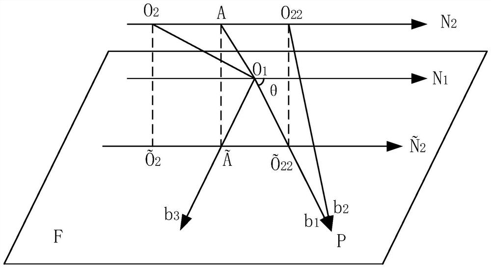
[0050] The present invention discloses a moving target detection system based on distributed synthetic aperture radar. According to a preferred embodiment, the moving target detection system based on distributed synthetic aperture radar includes at least one main star 100 and at least one Secondary star 200. The system also includes a clutter suppression module 400 and a pulse transmission module 600 arranged on the main / auxiliary satellite. The main star 100 transmits a signal through the pulse transmitting module 600, and the clutter suppression module 400 maximizes the signal-to-noise ratio of the output signal after reconstructing and generating a virtual uniform sampling signal based on the echo signal returned by the transmitted signal. After obtaining the velocity information of the moving target in the echo signal, the period of the pulse emission module 600 is adjusted so that the generated clutter equivalent radial velocity falls outside the preset range of the movin...

Embodiment 2

[0064] This embodiment may be a further improvement and / or supplement to Embodiment 1, and repeated content will not be repeated here. In the case of no conflict or contradiction, the whole and / or part of the content of the preferred implementations of other embodiments may serve as supplements to this embodiment.

[0065] According to a preferred embodiment, the system is also provided with a baseline compensation module 300 . Before the echo signal is detected by the moving target detection module 500, the echo signal is time-varying and / or mixed baseline compensation based on the trajectory parameters of the main star 100 and the spatial position relationship between the main star 100 and the auxiliary star 200 through the baseline compensation module 300. is a fixed along-track baseline to avoid degradation of the coherence of the resulting image. Preferably, the baseline compensation module 300 compensates the echo signals received under the time-varying and mixed baseli...


PUM


Abstract

The invention relates to a moving target detection system based on a distributed synthetic aperture radar, comprising at least one main star and at least one auxiliary star with the synthetic aperture radar as a payload, the system also includes a clutter suppression module arranged on the main / auxiliary star and A pulse transmission module, the main star transmits signals through the pulse transmission module, and the clutter suppression module maximizes the signal noise of the output signal after reconstructing and generating a virtual uniform sampling signal based on the echo signal signal reconstructor returned by the transmission signal ratio, and after obtaining the velocity information of the moving target in the echo signal, adjust the period of the pulse emission module so that the generated clutter equivalent radial velocity falls outside the preset range of the moving target velocity. The present invention can use the space-time adaptive processing technology to suppress the non-stationary clutter while setting the period of the pulse repetition period signal to avoid the moving target signal from being eliminated in the process of suppressing the clutter by the space-time adaptive processing technology, thereby reducing detection probability of failure.

Description

technical field [0001] The invention relates to the technical field of radar, in particular to a moving target detection system based on distributed synthetic aperture radar. Background technique [0002] Synthetic Aperture Radar (Synthetic Aperture Radar) ground moving target monitoring technology can image the observation scene with high resolution and at the same time complete the detection and positioning of ground targets. It is widely used in the fields of urban traffic monitoring and military reconnaissance and early warning. [0003] At present, the research on ground moving target detection technology of synthetic aperture radar is mainly divided into three categories: amplitude monitoring, phase monitoring and amplitude-phase joint detection. Amplitude detection is to use the amplitude information of the synthetic aperture radar image after adaptive clutter suppression to detect the target. Phase detection is mainly to perform interference processing on the synthe...

Claims


Application Information

Patent Timeline
Patent Type & Authority Patents(China)
IPC IPC(8): G01S13/90G01S13/58G01S7/02G01S7/36G01S7/41
CPCG01S13/9029G01S13/9023G01S13/582G01S13/589G01S7/023G01S7/36G01S7/414G01S7/415
Inventor 杜志贵杨峰任维佳陈险峰
Owner SPACETY CO LTD (CHANGSHA)
Why Eureka
Try Eureka