Reverse visual collimator

A collimator and reverse technology, applied in the direction of optics, optical components, measuring devices, etc., can solve the problems of eyepiece fatigue reading, low accuracy, instrument accuracy error, etc., to avoid human eye fatigue and danger, and save occupancy The effect of improving ground space and area, accuracy and uniformity

Pending Publication Date: 2019-11-15
南阳天正精科自动化设备有限公司
View PDF0 Cites 0 Cited by
  • Summary
  • Abstract
  • Description
  • Claims
  • Application Information

AI Technical Summary

Problems solved by technology

Disadvantages of this calibration method: large floor area, waste of space for batch debugging, and low accuracy, the human eye is prone to fatigue when observing the eyepiece with one eye for a long time, resulting in reading errors, and the requirements for repeatedly placing the instrument are very strict
Disadvantages of this correction method: the human eye is prone to fatigue when observing the eyepiece with one eye for a long time, resulting in reading errors, and the human eye needs to observe the eyepiece repeatedly during debugging, because the adjustment screw is very precise, and every time a little screw is adjusted, the human eye needs to observe the value through the eyepiece, and debug A good instrument needs to be observed several times or even more than a dozen times, which has a great impact on the speed of production and debugging
In addition, when adjusting the laser pointing point, use a light filter to block between the human eye and the eyepiece to prevent the laser from directly shining on the eyes and causing eye burns, which has a high risk factor.
In addition, the eyesight of each debugger is different, which will cause errors in the accuracy of the instrument debugged by different personnel.

Method used


Image

  • Reverse visual collimator
  • Reverse visual collimator

Examples


Embodiment Construction

[0014] In order to have a clearer understanding of the technical features, objectives and effects of the invention, the specific embodiments of the invention will now be described with reference to the accompanying drawings. In each figure, the same reference numerals represent the same components. In order to make the drawings concise, each figure only schematically shows the parts related to the present invention, and they do not represent the actual structure of the product as a product.

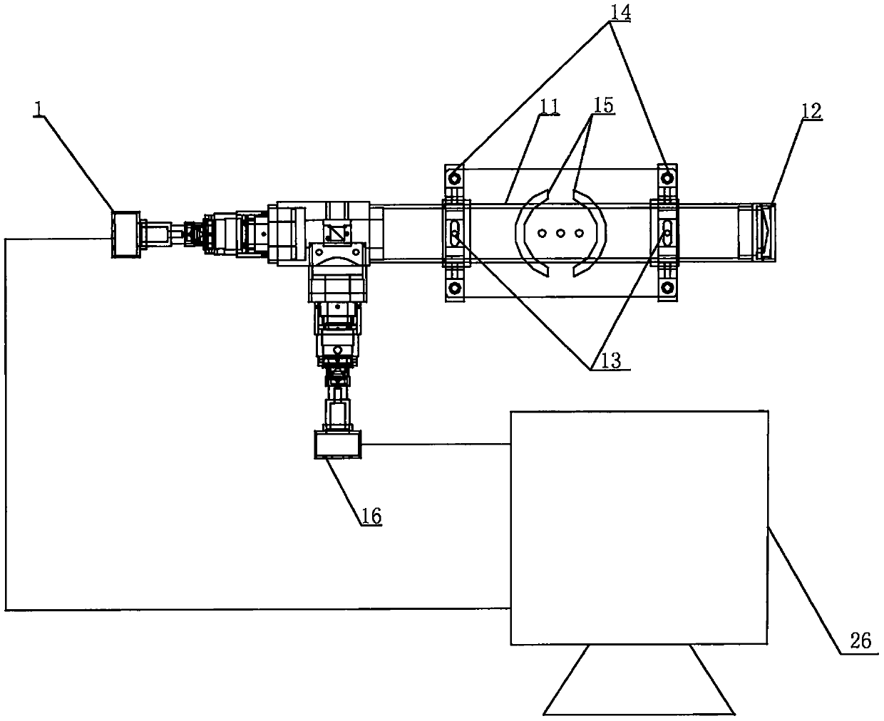
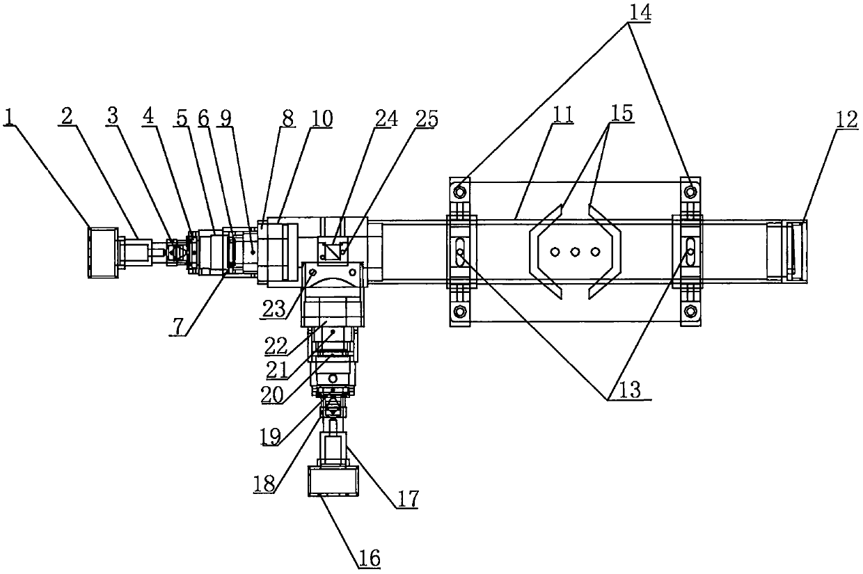
[0015] Such as figure 1 , 2 As shown, the present invention is an anti-visible collimator, including a collimator 11, the collimator 11 includes a laser display part, an optical display part and an optical part, the laser display part and the optical part are arranged on a horizontal line, The optical display part is vertically arranged between the laser display part and the optical part. The middle part of the collimator 11 is symmetrically provided with two collimator integrated fine-tuning...


PUM


Abstract

The invention belongs to a reverse visual collimator. The reverse visual collimator comprises a collimator 11, wherein the collimator 11 comprises a laser display part, an optical display part and anoptical part, and is characterized in that the laser display part and the optical part are arranged on a horizontal line; the optical display part is vertically arranged between the laser display partand the optical part; two collimator integral fine adjustment devices 13 are symmetrically arranged in the middle of the collimator 11; two collimator integral rough adjustment devices 14 are arranged at the lower parts of the two collimator integral fine adjustment devices 13; and a collimator integral fixing device 15 is arranged between the two collimator integral rough adjustment devices 14.The reverse visual collimator has the advantages that the structure is simple, the design is reasonable, the occupied space and area are greatly saved, the debugging precision is high, the debugging speed is high, the error is small, human eye fatigue and the danger are avoided, the vision difference of human eyes is eliminated, and the accuracy and the uniformity of mapping instrument are greatlyimproved.

Description

Technical field [0001] The invention belongs to the field of optoelectronic technology, and specifically relates to an anti-visible parallel light tube. Background technique [0002] Currently, the surveying and mapping instrument industry has the following status quo: Surveying and mapping instruments include optical level, electronic theodolite, total station, vertical collimator, etc. These surveying and mapping instruments generally consist of an optical reference part and a laser pointing part, which must be calibrated and adjusted to a unified reference during production or after-sales maintenance. There are currently two calibration methods: 1. The calibration method using three points and one line is to find an empty or long workshop, set a target with a cross scale at 50 meters and 100 meters, or use a mirror to reflect To reach a longer distance, use a more accurate level in advance, and adjust the three cross targets to a uniform horizontal line through the crosshairs...

Claims


Application Information

Patent Timeline
Patent Type & Authority Applications(China)
IPC IPC(8): G01C25/00G02B27/34G02B27/36
CPCG01C25/00G02B27/34G02B27/36
Inventor 王林
Owner 南阳天正精科自动化设备有限公司
Why Eureka
Try Eureka