
Filling deflagration energy accumulation volume fracturing method in cracks

A volumetric fracturing and filling technology, which is applied in chemical instruments and methods, mining fluids, earth drilling, etc., can solve the problems of unclear detonation position, wellbore damage, and inability to completely detonate explosives, etc., and achieves convenient and cost-effective operation , saving dosage and increasing the complexity of cracks

Active Publication Date: 2019-11-15
CHINA UNIV OF PETROLEUM (EAST CHINA)
View PDF4 Cites 7 Cited by
  • Summary
  • Abstract
  • Description
  • Claims
  • Application Information

AI Technical Summary

Problems solved by technology

The detonation position of the traditional detonation technology in the wellbore is not clear, and the explosiv

Method used


Image

  • Filling deflagration energy accumulation volume fracturing method in cracks
  • Filling deflagration energy accumulation volume fracturing method in cracks
  • Filling deflagration energy accumulation volume fracturing method in cracks

Examples


Embodiment 1

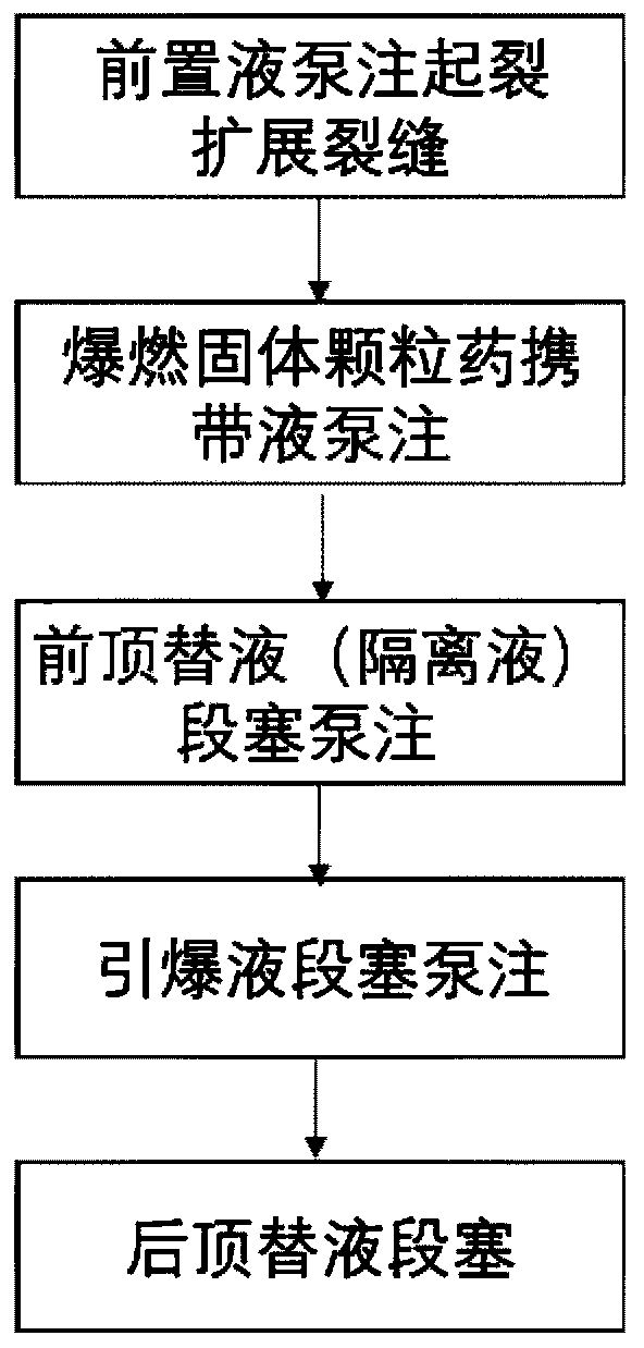
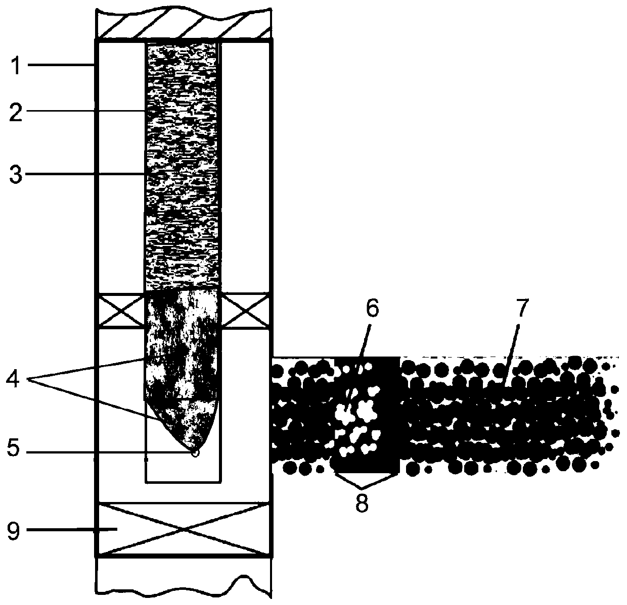
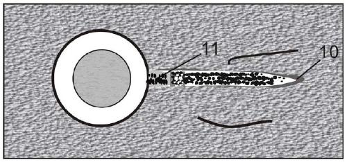
[0036] Such as figure 1 , figure 2 The shown is an oil and gas layer fracturing stimulation of an in-fracture filling type deflagration energy-gathering volume fracturing process, which uses an in-fracture filling method to press a deflagration system into the fractured reservoir where the target well is located. The steps are as follows:

[0037] An in-fracture filling type deflagration energy-gathering volume fracturing method, the method includes the following steps:

[0038] (1) The pre-fluid is pumped to initiate and expand cracks; the composition of the pre-fluid is guar gum fracturing fluid with a viscosity of 60-100mPa.s. The dosage is calculated and determined according to the crack design scale and crack propagation simulation.

[0039] (2) The deflagration solid granular drug is pumped with sand-carrying fluid, and the solid granular drug is carried to fill the cracks; the sand-carrying fluid is self-breaking cross-linked guar gum fracturing fluid. The solid gr...

Embodiment 2

[0060] A crevice-filled deflagration energy-gathering volumetric fracturing method, the steps of which are as described in Example 1, except that the mass ratio of granular propellant powder to aluminum powder in step (2) is 1:1.

Embodiment 3

[0062] An in-fracture filling deflagration energy-gathering volumetric fracturing method, the steps of which are as described in Example 1, except that the injection amount of the pre-displacement fluid in step (3) is 35% of the wellbore volume of the target well.


PUM

PropertyMeasurementUnit
Viscosityaaaaaaaaaa
Granularityaaaaaaaaaa
Densityaaaaaaaaaa

Abstract

The invention relates to a filling deflagration energy accumulation volume fracturing method in cracks. The filling deflagration energy accumulation volume fracturing method comprises the following steps that (1) prepad fluid pumping is performed, and crack initiation and propagation of the cracks are performed; (2) solid particle gunpowder is deflagrated and sand-carrying fluid pumping is performed, and the solid particle gunpowder is carried to fill the cracks; (3) front displacement fluid slug is subjected to pumping, and the sand carrying fluid is displaced into the cracks to separate detonation fluid and the sand carrying fluid; (4) detonation fluid is subjected to slug pumping to detonate the solid particle gunpowder in the cracks; and (5) rear displacement fluid slug is subjected topumping. According to the filling deflagration energy accumulation volume fracturing method, detonation particle gunpowder is injected into the cracks together with the solid particle gunpowder, thenliquid detonating fluid is used for squeezing slugs into the cracks and reacting with the detonation particle gunpowder to release the energy to detonate the solid particle gunpowder filling cracks,complexity of the cracks can be increased on a large scale, compared with conventional hydraulic fracturing, a propping agent in the cracks is subjected to deflagration fracturing, a plurality of random cracks can be stimulated on both sides of a main crack, three-dimensional volume reconstruction is formed, and the effect of fracturing reconstruction is greatly improved.

Description

technical field [0001] The invention relates to a filling-type deflagration energy-gathering volume fracturing used in oil and natural gas reservoir fracturing reconstruction, and belongs to the technical field of oilfield fracturing. Background technique [0002] After the oil and gas field enters the middle and late stage, the output drops significantly or even shuts down. It is urgent to take some measures to improve the permeability of the formation. However, the hydraulic fracturing and acidizing technologies currently used to stimulate the reservoir have many limitations, resulting in ineffective development. The proposal of intralayer deflagration fracturing technology effectively solves such problems. In the selection of propellant, although liquid propellant has advantages in indicators such as effective detonation time and operating cost, compared with solid propellant, the transportation of liquid propellant is more complicated, and the configuration process is cu...

Claims


Application Information

Patent Timeline
IPC IPC(8): E21B43/263C06B33/12C06B23/00C09K8/68C09K8/90
CPCC06B23/00C06B23/007C06B33/12C09K8/685C09K8/90E21B43/263
Inventor 吴飞鹏杨维刘静丁乾申李德
Owner CHINA UNIV OF PETROLEUM (EAST CHINA)
Learn More