Energy-absorbing and decompressing protective frame device installed on the rear frame of heavy-duty vehicles

A technology for heavy-duty vehicles and protective frames, which is applied to vehicle safety arrangements, bumpers, and vehicle components. It can solve the problems of flexibility, low safety protection, single shock-absorbing structure, and poor effect, and achieve good shock-absorbing effects. High security and the effect of preventing subsequent impact

Active Publication Date: 2021-04-16
徐州巴布工程机械有限公司
View PDF8 Cites 0 Cited by
  • Summary
  • Abstract
  • Description
  • Claims
  • Application Information

AI Technical Summary

Problems solved by technology

[0004] One is that the flexibility and safety protection are low. The main focus of the existing devices is how to cushion, mainly through elastic telescopic rods or springs, to perform a certain degree of cushioning and shock absorption in the event of a vehicle collision accident. It cannot start from a fundamental point of view. For example, in the event of a vehicle collision accident, through structural improvements, the direction of the impact force is changed, and the force is unloaded to minimize the damage caused by the impact; moreover, shock absorption The structure is relatively simple and the effect is poor. When the front of the vehicle is hit, it is not possible to use multiple shock-absorbing structures and multiple shock-absorbing structures to cooperate with each other to reduce the impact of the impact to the greatest extent to improve safety.

Method used


Image

  • Energy-absorbing and decompressing protective frame device installed on the rear frame of heavy-duty vehicles
  • Energy-absorbing and decompressing protective frame device installed on the rear frame of heavy-duty vehicles
  • Energy-absorbing and decompressing protective frame device installed on the rear frame of heavy-duty vehicles

Examples


Embodiment

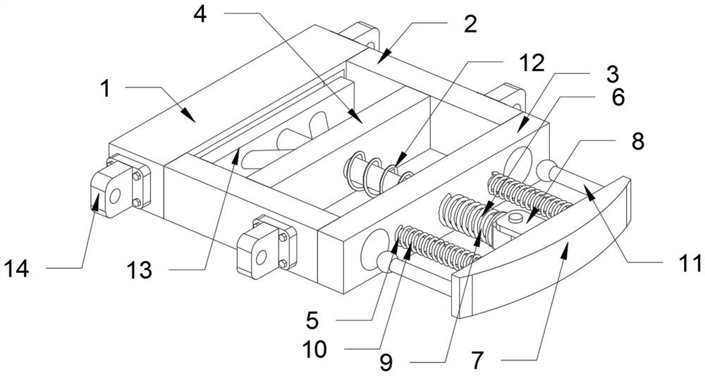
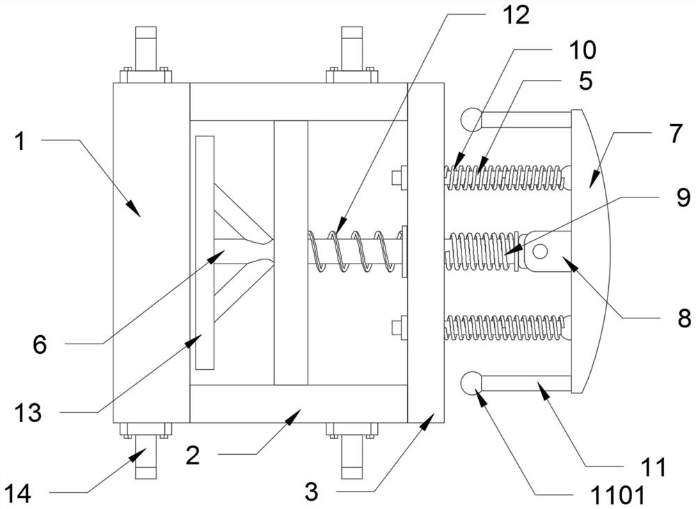
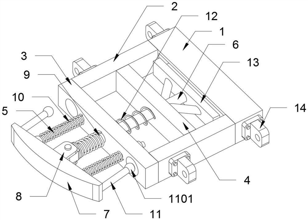
[0034] as attached figure 1 to attach Figure 8 Shown:

[0035]The present invention provides an energy-absorbing and decompression protective frame device installed on the rear frame of a heavy-duty vehicle, comprising: a bottom plate 1, a rectangular groove 101, a rectangular rubber block 102, a support column 2, a rectangular plate A3, a circular hole 301, a cylindrical rubber 302, rectangular plate B4, cylindrical rod A5, iron ball A501, cylindrical rod B6, annular baffle A601, annular baffle B602, force plate 7, semicircular groove 701, rotating connection seat 8, spring A9, spring B10, cylindrical rod C11, iron ball B1101, spring C12, rectangular plate C13 and holder 14; the front end of the base plate 1 is provided with a rectangular groove 101, and a piece of the rectangular groove 101 is provided in the rectangular groove 101. Rectangular rubber block 102; the left end surface and the right end surface of the base plate 1 are all fixedly connected with a described f...


PUM


Abstract

The invention provides an energy-absorbing and decompression protective frame device installed on the rear frame of a heavy-duty vehicle, comprising: a base plate, a rectangular plate C and a fixing seat; the front end of the base plate is provided with a rectangular groove; the cylindrical rod B is slidingly connected in the middle of the rectangular plate A and the rectangular plate B. The present invention has high safety. When the left side or the right side of the force plate is hit, the force plate can be rotated left or right along the position of the rotating connection seat, and the force plate can be rotated left or right. When turning to the right, the spring B on the cylindrical rod A can be compressed for shock absorption. At this time, the iron ball A on the cylindrical rod A can slide along the semicircular groove. When the force plate is under the action of the impact force When continuing to rotate, the iron ball A on the cylindrical rod A compresses the cylindrical rubber on the rectangular plate A to perform buffering and shock absorption again. Under the action of the impact, the force plate is inclined, and the impact force can be directed to the left or The force is unloaded on the right side to prevent the subsequent impact of the impact force.

Description

technical field [0001] The invention belongs to the technical field of automobile decompression protection devices, and more specifically relates to an energy-absorbing decompression protection frame device installed on the rear frame body of a heavy-duty vehicle. Background technique [0002] With the continuous improvement of living standards and machinery manufacturing levels, various types of vehicles on the road are also increasing. Driven by the increasing number of vehicles, the number of vehicle accidents is also increasing. Bar, the protective bar used in automobiles at present, most of the bumpers use steel railing-like devices. When the car collides with other objects, it only plays the role of head-to-head and force-blocking, although it can reach a certain extent The purpose of protecting the car, but this protective device can not buffer, absorb and consume the impact force well, and the effect of shock absorption and decompression is not good. [0003] Based ...

Claims


Application Information

Patent Timeline
Patent Type & Authority Patents(China)
IPC IPC(8): B60R19/02
CPCB60R19/023B60R2019/026
Inventor 石思思
Owner 徐州巴布工程机械有限公司
Why Eureka
Try Eureka