
Bag grabbing mechanical arm for sludge bag breaking equipment

A manipulator and bag breaking technology, which is applied to manipulators, program-controlled manipulators, chucks, etc., can solve the problems of incapable sludge bag clamping, rigid structure, and inconvenience for the rapid movement of manipulators.

Pending Publication Date: 2019-11-15
四川同人精工科技有限公司
View PDF6 Cites 10 Cited by
  • Summary
  • Abstract
  • Description
  • Claims
  • Application Information

AI Technical Summary

Problems solved by technology

[0002] In the sewage treatment industry, the current sludge drying and incineration process for sludge treatment has been widely used in the industry. During the transfer of sludge from sewage plants to sludge plants, ton bags are often used to hold the sludge and then transport it to the sewage treatment plant. In the sludge treatment plant, the bag-grabbing manipulator grabs the sludge belt into the sludge bag breaking equipment for processing during sludge treatment. The existing bag-grabbing manipulator has a rigid structure, which is not convenient for the rapid movement of the manipulator, and it is not convenient for the manipulator. The height can be adjusted flexibly, which makes it impossible to work on workbenches of different heights, and it is not convenient to adjust the opening size of the gripping claws at multiple angles, and it is not possible to grip sludge bags of different sizes

Method used


Image

  • Bag grabbing mechanical arm for sludge bag breaking equipment
  • Bag grabbing mechanical arm for sludge bag breaking equipment
  • Bag grabbing mechanical arm for sludge bag breaking equipment

Examples


Embodiment Construction

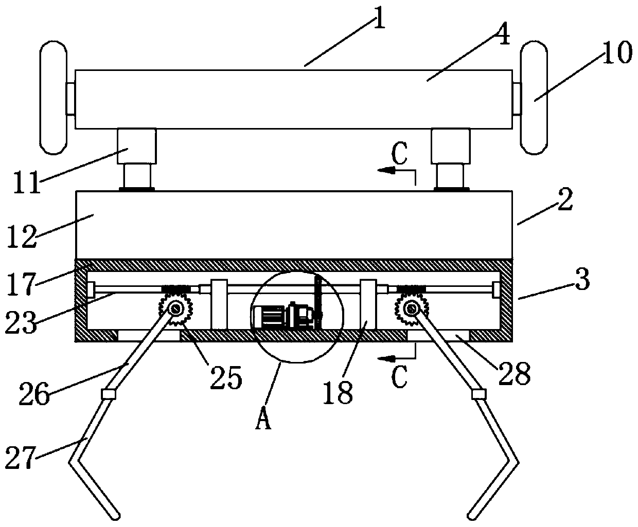
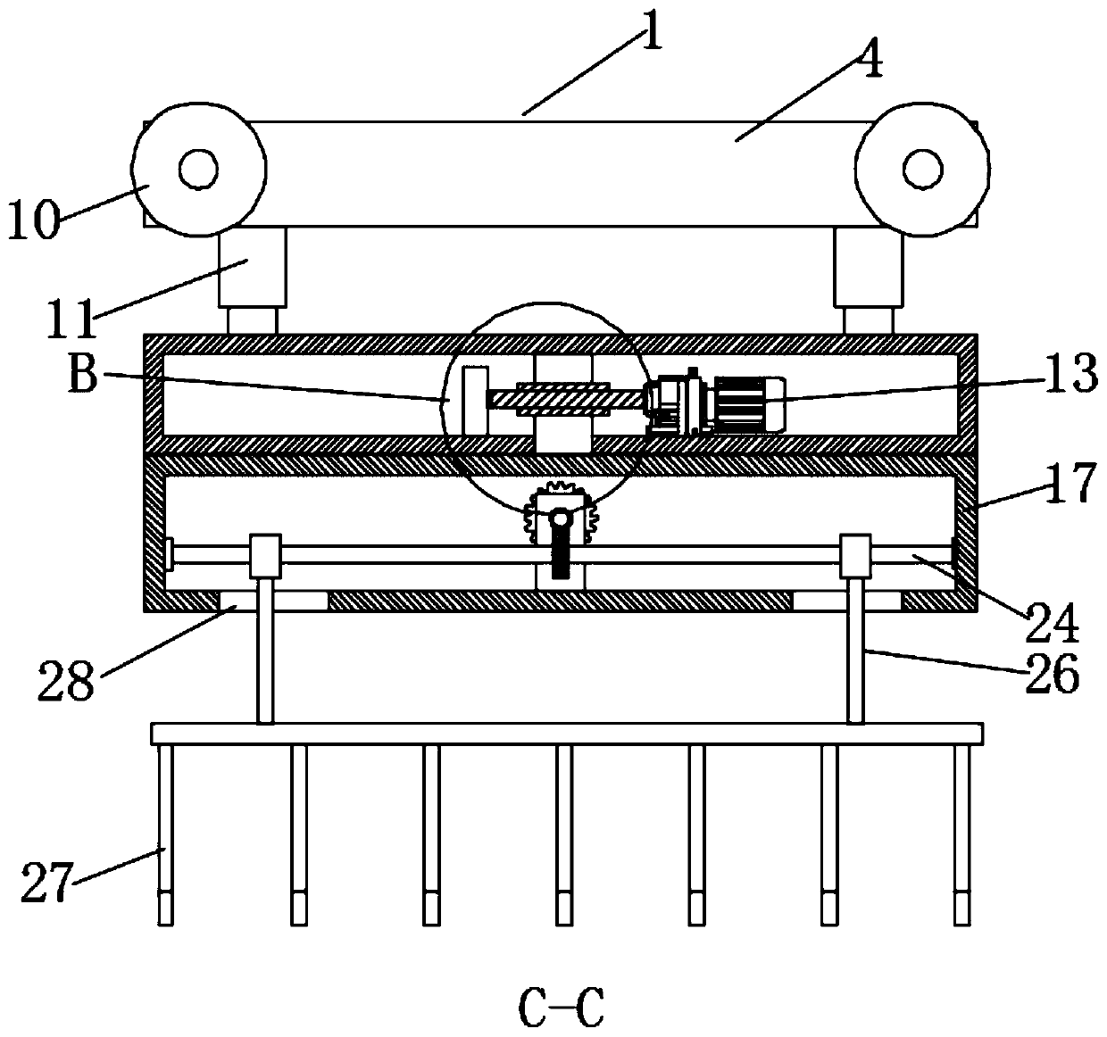
[0021] like Figure 1-5 As shown, this specific embodiment adopts the following technical solutions: a bag grabbing manipulator for sludge bag breaking equipment, including a moving mechanism 1, a steering mechanism 2 and a grabbing mechanism 3, and the bottom of the moving mechanism 1 is provided with a steering mechanism 2 , the bottom of the steering mechanism 2 is provided with a grasping mechanism 3, and the moving mechanism 1 is composed of a moving box 4, a driven shaft 5, a driving shaft 6, a driven bevel gear 7, a driving motor 8, a driving bevel gear 9 and The drive wheel 10 is composed of one end inside the moving box 4 which is rotatably connected with a driven shaft 5, and one end which is far away from the driven shaft 5 inside the moving box 4 is rotatably connected with a driving shaft 6, and the middle part of the driving shaft 6 A driven bevel gear 7 is fixedly connected, and a driving motor 8 is fixedly installed inside the moving box 4, and the output end o...


PUM


Abstract

The invention discloses a bag grabbing mechanical arm for sludge bag breaking equipment. The mechanical arm comprises a moving mechanism, a steering mechanism and a grabbing mechanism, wherein the steering mechanism is arranged at the bottom of the moving mechanism, the grabbing mechanism is arranged at the bottom of the steering mechanism, and the moving mechanism is composed of a movable box body, a driven shaft, a driving shaft, a driven bevel gear, a driving motor, a driving bevel gear and a driving wheel. According to the mechanical arm, the driving motor and the driving shaft are arranged, the mechanical arm can be driven to move transversely under the action of the driving motor so that the mechanical arm can move rapidly; a lifting hydraulic cylinder is arranged, the height of themechanical arm can be flexibly adjusted, so that the mechanical arm can work for working tables with different heights; and a steering motor, a rotary main shaft, a transmission worm and a transmission worm wheel are arranged, the size of the opening of a clamping claw can be adjusted in multiple angles under the matching of the transmission worm and the transmission worm wheel so that sludge bagswith different sizes can be clamped by the clamping claw.

Description

Technical field: [0001] The invention belongs to the technical field of mechanical equipment, in particular to a bag grabbing manipulator for sludge bag breaking equipment. Background technique: [0002] In the sewage treatment industry, the current sludge drying and incineration process for sludge treatment has been widely used in the industry. During the transfer of sludge from sewage plants to sludge plants, ton bags are often used to hold the sludge and then transport it to the sewage treatment plant. In the sludge treatment plant, the bag-grabbing manipulator grabs the sludge belt into the sludge bag breaking equipment for processing during sludge treatment. The existing bag-grabbing manipulator has a rigid structure, which is not convenient for the rapid movement of the manipulator, and is not convenient for the manipulator. The height of the machine can be flexibly adjusted, and it cannot be used for workbenches of different heights, and it is not convenient to adjust...

Claims


Application Information

Patent Timeline
IPC IPC(8): B25J9/12B25J9/14B25J15/02
CPCB25J9/123B25J9/144B25J15/0253
Inventor 蒋开宇程春林李晨浩
Owner 四川同人精工科技有限公司
Learn More