
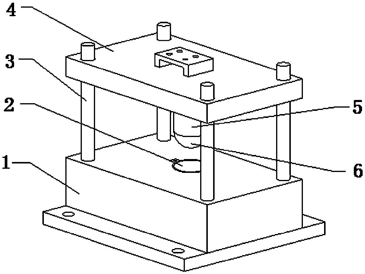
Stamping die of back plate convex hull

A stamping die and convex hull technology, which is applied in the field of backplane processing equipment, can solve the problems of lower maintenance costs, the need for overall replacement, and high maintenance costs, and achieve the effects of reduced maintenance costs, convenient replacement, and convenient connection

Pending Publication Date: 2019-11-15
重庆嘉泰罗光电科技有限公司
View PDF0 Cites 0 Cited by
  • Summary
  • Abstract
  • Description
  • Claims
  • Application Information

AI Technical Summary

Problems solved by technology

[0003] Aiming at the deficiencies in the prior art, the object of the present invention is to provide a stamping die for the convex hull of the backplane, so as to solve the problem that the structure of the mold for processing the convex hull of the backplane proposed in the above-mentioned background technology is fixed, resulting in the structure used for stamping the convex hull on the mold After wear and tear, it needs to be replaced as a whole, and the maintenance cost is high. The invention realizes the partial replacement of the worn part and reduces the maintenance cost

Method used


Image

  • Stamping die of back plate convex hull
  • Stamping die of back plate convex hull
  • Stamping die of back plate convex hull

Examples


Embodiment Construction

[0019] Before describing the embodiments in detail, it should be understood that the present invention is not limited to the detailed structures or arrangements of elements described herein below or in the accompanying drawings. The present invention can be an embodiment implemented in other ways. Also, it should be understood that the phraseology and terminology used herein are for descriptive purposes only and should not be interpreted as limiting. The terms "including", "comprising", "having" and similar expressions used herein are meant to include the items listed thereafter, their equivalents and other additional items. In particular, when "a certain element" is described, the present invention does not limit the number of the element to one, but may also include a plurality.

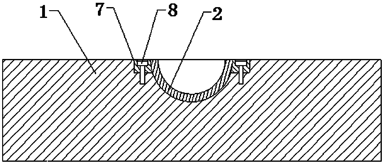
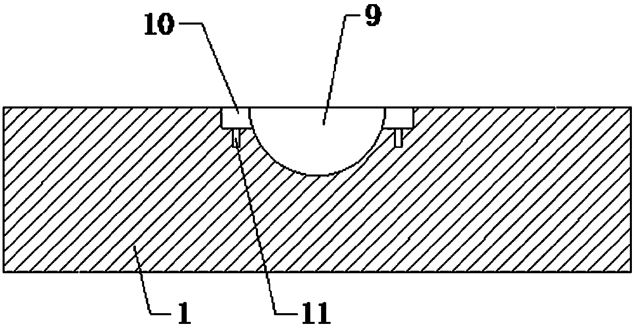
[0020] see Figure 1-Figure 5 , the present invention provides a technical solution: the stamping die of the convex hull of the back plate includes a bottom mold 1, and guide columns 3 are instal...


PUM


Abstract

The invention provides a stamping die of a back plate convex hull. The stamping die comprises a bottom die, wherein guide columns are mounted at four corners of the upper end surface of the bottom die, a pressing plate is arranged on the upper side of the bottom die, and the upper ends of the guide columns penetrate through the pressing plate; a ball groove is formed in the upper end surface of the bottom die, a hemispherical cover is formed in the ball groove, positioning grooves are formed in the left side and the right side of the inner surface of the ball groove, a first threaded blind holes are formed in the lower end surface of the interior of the positioning grooves, positioning plates are fixed on the left side and the right side of the outer surface of the hemispherical cover, thepositioning plates are arranged in the positioning grooves, countersunk head holes are formed in the upper end surfaces of the positioning plates, inner hexagonal bolts are formed in the countersunkhead holes, a stamping rod is arranged in the middle of the lower end surface of the pressing plate, a hemispherical head is arranged on the lower end of the stamping rod, a second threaded blind holeis formed in the middle position of the upper end surface of the hemispherical head, and a stud is fixed at the lower end of the stamping rod. Compared with the prior art, the stamping die has the beneficial effects that local replacement of the worn part is realized, and the maintenance cost is reduced.

Description

technical field [0001] The invention relates to a stamping die for a convex hull of a backboard, which belongs to the field of backboard processing equipment. Background technique [0002] The display includes a panel and a backlight module. The backlight module is composed of an optical film, a light guide plate, a backlight unit, and a backplane. The backplane, as the main supporting mechanism of the entire backlight module, mainly plays a role in protecting the optical components in the display. , At present, the structure of the mold used to process the convex hull of the back plate is fixed, resulting in the structure of the mold used for stamping the convex hull being worn and needs to be replaced as a whole, and the maintenance cost is high. Contents of the invention [0003] Aiming at the deficiencies in the prior art, the object of the present invention is to provide a stamping die for the convexity of the backplane, so as to solve the problem that the structure o...

Claims


Application Information

Patent Timeline
Patent Type & Authority Applications(China)
IPC IPC(8): B21D22/04B21D37/10
CPCB21D22/04B21D37/10
Inventor 刘波杨建波朱雄史二强汪长生
Owner 重庆嘉泰罗光电科技有限公司
Learn More