Eureka AIR delivers breakthrough ideas for toughest innovation challenges, trusted by R&D personnel around the world.

Broadband switching method, user terminal and network side equipment

A technology for network-side equipment and user terminals, which is applied in the directions of multiple use of transmission paths, transmission monitoring, and digital transmission systems, and can solve the problem that the switching principle is not clearly given.

Active Publication Date: 2019-11-12
CHINA MOBILE COMM LTD RES INST +1
View PDF4 Cites 5 Cited by
  • Summary
  • Abstract
  • Description
  • Claims
  • Application Information

AI Technical Summary

Problems solved by technology

[0004] In the existing technical solutions, only the relevant signaling and process of BWP handover are given, but the principle of BWP handover is not clearly given. An intuitive BWP handover principle is to dynamically or semi-statically perform different sizes according to the bandwidth requirements of the UE. For BWP switching, the base station or UE only needs to perform BWP switching according to the BWP indicated by high-level signaling. However, the problem with this technical solution is that if the four BWP bandwidths configured by the UE are the same, it cannot be simply based on the UE bandwidth. switch on demand

Method used


Image

  • Broadband switching method, user terminal and network side equipment
  • Broadband switching method, user terminal and network side equipment
  • Broadband switching method, user terminal and network side equipment

Examples


Embodiment 1

[0159] Such as Figure 5 As shown, the four BWPs (BWP1, BWP2, BWP3, and initial BWP) configured for the UE overlap with each other, and there is one BWP3 that can completely cover other BWPs.

[0160] The base station configures a measurement interval through the high-level signaling BWP-measGapConfig. In this measurement interval, the base station configures the UE to send aperiodic SRS on BWP3. The base station estimates the channel quality of the entire BWP3 according to the received SRS, and can know the channel quality in BWP3. A good segment, and then select the BWP that can be activated according to the size of the UE frequency band requirement and the location of each BWP center frequency point. In this embodiment, the frequency band with better channel quality is the frequency band covered by BWP1, so the base station passes the RRC signal Command or DCI indicates to activate BWP1, and the UE switches from the initial BWP to BWP1 with better channel quality.

Embodiment 2

[0162] Such as Figure 6 As shown, the four BWPs (BWP1, BWP2, BWP3, and initial BWP) configured for the UE overlap with each other, but there is no situation where one BWP can completely cover other BWPs.

[0163] The base station configures three measurement intervals through the high-layer signaling BWP-measGapConfig, and configures SRS resource for different BWPs within the three measurement intervals, for example, configuring UE to send aperiodic SRS on BWP1, BWP2, and BWP3. The base station estimates the channel quality of each BWP through the received SRS, and instructs the UE to switch to BWP2 with better channel quality through DCI.

Embodiment 3

[0165] When the SRS resource used for inactive BWP channel quality measurement is an aperiodic reference signal, the base station configures the measurement interval through the high-level signaling BWP-measGapConfig, and at the same time triggers the UE to send the pre-configured After that, the base station estimates the channel quality of the BWP according to the received SRS, and instructs the UE to switch to the active BWP with better channel quality according to the channel quality.


PUM


Abstract

The invention provides a broadband switching method, a user terminal and network side equipment, and belongs to the technical field of wireless communication. The broadband switching method applied tothe network side equipment comprises the steps of configuring a measurement interval, and adopting the measurement interval for the network side equipment to carry out channel measurement on a non-activated bandwidth part (BWP). The broadband switching method applied to the user terminal comprises the following steps: receiving configuration information of a measurement interval sent by network side equipment through a first high-level signaling, wherein the measurement interval is used for the user terminal to send an uplink sounding reference signal SRS on an inactive BWP. Through the technical scheme of the invention, the BWP to be switched can be determined through channel quality measurement.

Description

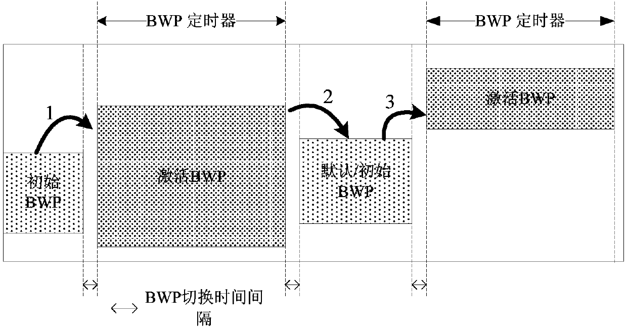
technical field [0001] The present invention relates to the technical field of wireless communication, in particular to a broadband switching method, user terminal and network side equipment. Background technique [0002] Channel capacity is directly proportional to bandwidth and signal noise ratio (SNR). In order to meet the Gbps-level data rate of 5G network, a larger bandwidth is required. The higher the frequency, the larger the bandwidth and the higher the channel capacity. High-frequency continuous bandwidth has become an inevitable choice for 5G. In large bandwidth operation, a user equipment (UE) can be configured with up to 4 bandwidth parts (bandwidth part, BWP), but in the R15 standard, data can only be transmitted in one BWP, that is, at most one BWP can be activated at a time. BWP. [0003] Such as figure 1 In the BWP operation flow chart shown, in the UE initial access phase, an initial BWP is configured through high-level signaling for the initial access pr...

Claims


Application Information

Patent Timeline
IPC IPC(8): H04B17/382H04B17/309H04L5/00
CPCH04L5/0048H04B17/309H04B17/382
Inventor 王爱玲倪吉庆周伟王森
Owner CHINA MOBILE COMM LTD RES INST
Why Eureka
Eureka Blog
Learn More