
Telescopic wireless charger and support box

A wireless charger and wireless charging technology, which is applied in the direction of current collectors, circuits, electric vehicles, etc., can solve problems such as the use of mobile phone brackets, mobile phone screens, wireless chargers and accessories that are inconvenient to carry, and reduce the cost of packaging materials. Energy Saving Effect

Pending Publication Date: 2019-11-12
TEN PAO ELECTRONICS HUIZHOU +1
View PDF0 Cites 0 Cited by
  • Summary
  • Abstract
  • Description
  • Claims
  • Application Information

AI Technical Summary

Problems solved by technology

[0008] The purpose of the present invention is to solve the problem of existing wireless chargers for mobile phones. The mobile phone is aligned with the wireless charging area by feeling. It often needs to be moved once or twice before it can be successfully charged. The mobile phone is easy to deviate from the charging area due to a slight external force. When the charging area deviates greatly, the mobile phone and the charging stand have been establishing communication, and the mobile phone screen will be on and off for a while, and the vicious cycle will seriously damage the life of the mobile phone. The wireless charger and accessories are not convenient to carry, and cannot be used as a mobile phone stand.

Method used


Image

  • Telescopic wireless charger and support box
  • Telescopic wireless charger and support box
  • Telescopic wireless charger and support box

Examples


Embodiment Construction

[0041] The following will clearly and completely describe the technical solutions in the embodiments of the present invention with reference to the drawings in the embodiments of the present invention. Apparently, the described embodiments are only some of the embodiments of the present invention, but not all of them. Based on the embodiments of the present invention, all other embodiments obtained by persons of ordinary skill in the art without creative efforts fall within the protection scope of the present invention.

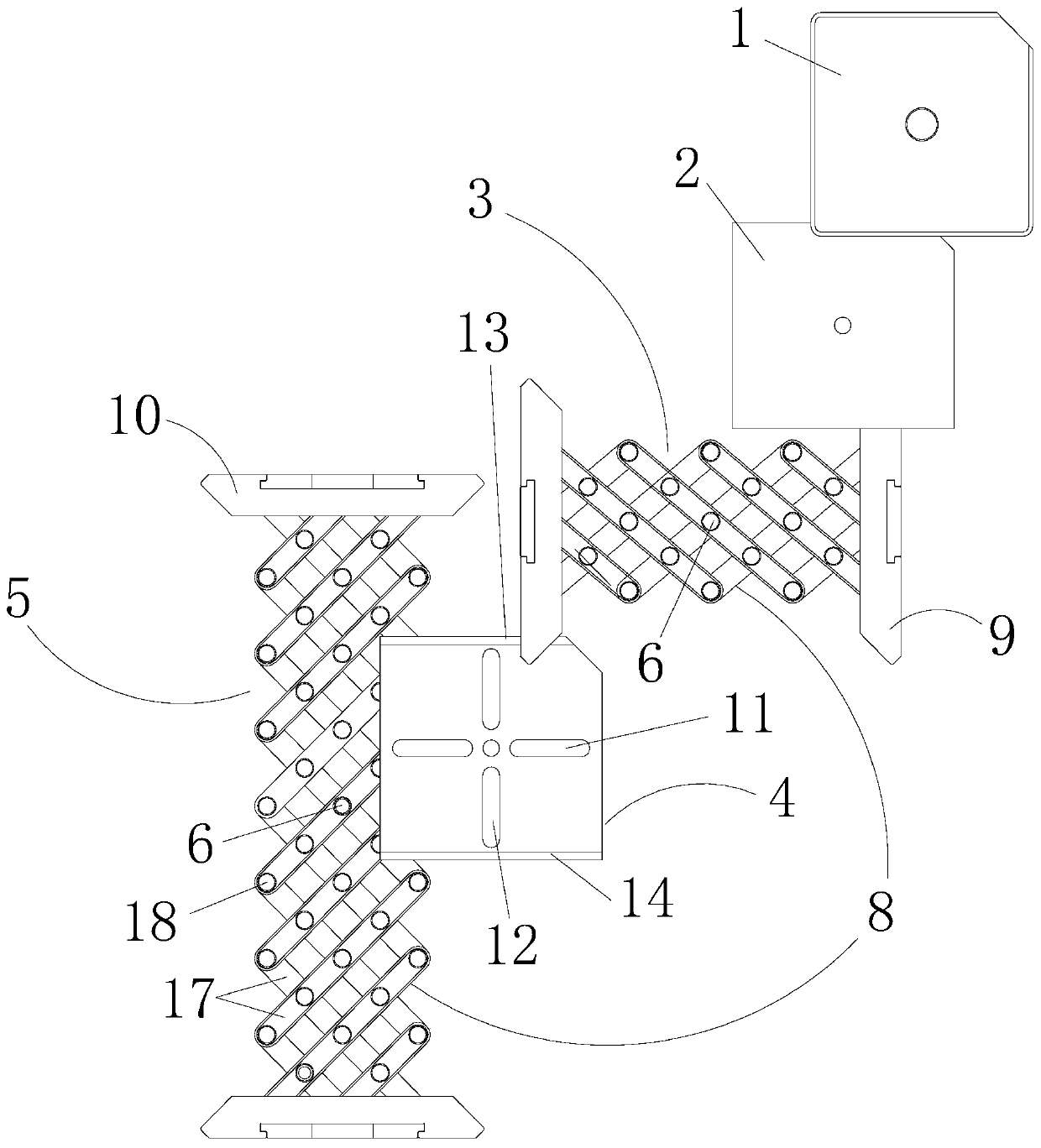
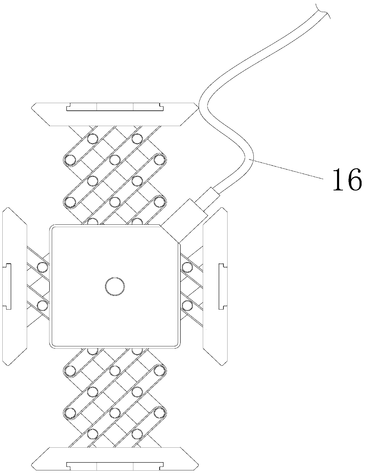
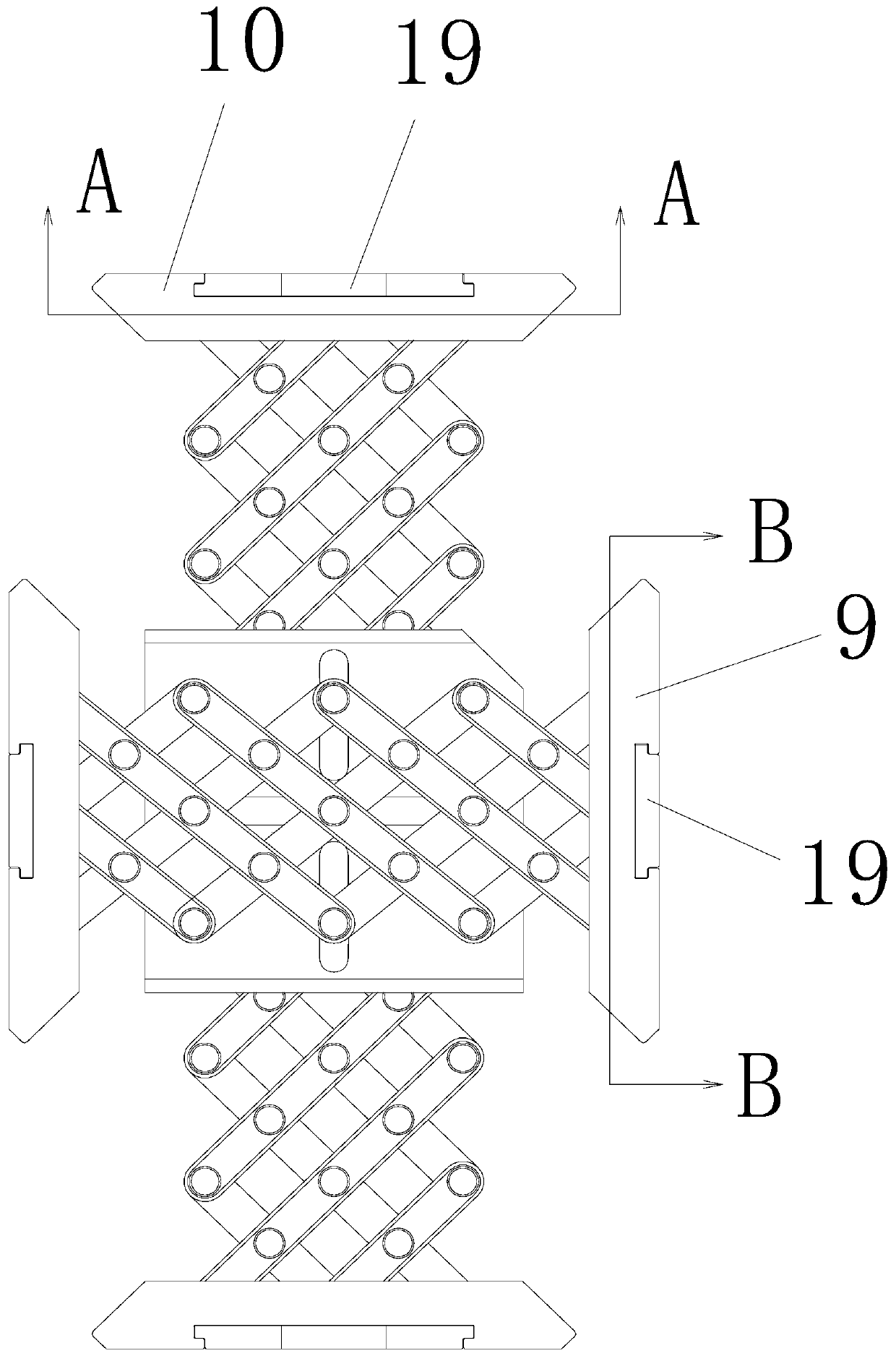
[0042] Such as Figures 1 to 6 As shown, a retractable wireless charger includes a wireless charging box 1, a spacer 2 located on the back of the wireless charging box 1, a horizontal telescopic component 3 located on the back of the spacer 2, and a limiting piece 4 located on the back of the horizontal telescopic component 3 , the longitudinal telescopic assembly 5 located at the back of the spacer 4 also includes a hollow rivet 6 passing through the center...


PUM


Abstract

The invention relates to a telescopic wireless charger. The telescopic wireless charger comprises a wireless charging box, an isolation piece, a horizontal telescopic assembly, a limitation piece, a longitudinal telescopic assembly, also comprises a hollow rivet and also comprises a pin, wherein the isolation piece is arranged on a back surface of the wireless charging box, the horizontal telescopic assembly is arranged on a back surface of the isolation piece, the limitation piece is arranged on a back surface of the horizontal telescopic assembly, the longitudinal telescopic assembly is arranged on a back surface of the limitation piece, the hollow rivet forwards and sequentially penetrates through the limitation piece, the horizontal telescopic assembly and the isolation piece from thecenter of a back surface of the longitudinal telescopic assembly, and the pin penetrates from one end of the hollow rivet in the center of the back surface of the longitudinal telescopic assembly, penetrates out of the other end of the hollow rivet in the center of the isolation piece and is screwed into a central hole in the back surface of the wireless charging box. A support box comprises a boxcover and a box body, wherein the wireless charger, a switch power supply, a charging line, the pin and other parts can be accommodated in the box body. Two ends of a telescopic network chain can simultaneously extend and contract when a clamping arm at an arbitrary end is pulled, the length of the clamping arm can be locked at any time by a locking mechanism on the clamping arm, and the telescopic wireless charger is applicable to mobile phones in different sizes.

Description

technical field [0001] The invention relates to the field of mobile phone wireless chargers, in particular to a retractable wireless charger and a bracket box. Background technique [0002] There are many types of mobile phone wireless chargers on the market, including plane type, desktop bracket type, vehicle bracket type, etc. The bracket fixing methods mainly include hook clip type and adsorption type. However, these existing brackets have the following defects: [0003] (1) The mobile phone is aimed at the wireless charging area by feeling, and it often needs to be moved once or twice before it can be successfully charged; [0004] (2) The mobile phone is easy to deviate from the charging area due to slight external force; [0005] (3) There is a large offset between the mobile phone and the charging area, and there will be a communication between the mobile phone and the charging stand, and the screen of the mobile phone will be on and off for a while, and the vicious ...

Claims


Application Information

Patent Timeline
Patent Type & Authority Applications(China)
IPC IPC(8): H01R13/502H01R13/514H01R13/627H01R13/629H02J7/00H02J50/90H04M1/04
CPCH01R13/514H01R13/502H01R13/627H01R13/629H02J50/90H02J7/0044H04M1/04
Inventor 严崇俊伍公理雷剑洪瑞德杨冰冰
Owner TEN PAO ELECTRONICS HUIZHOU
Learn More