Remote transmission gas density relay system and calibration method thereof
A technology of gas density and relay, which is applied in the field of electric power, can solve the problems of potential safety hazards, reduction of insulation strength on the surface of insulating parts, hazards, etc.
- Summary
- Abstract
- Description
- Claims
- Application Information
AI Technical Summary
Problems solved by technology
Method used
Image
Examples
Embodiment 1
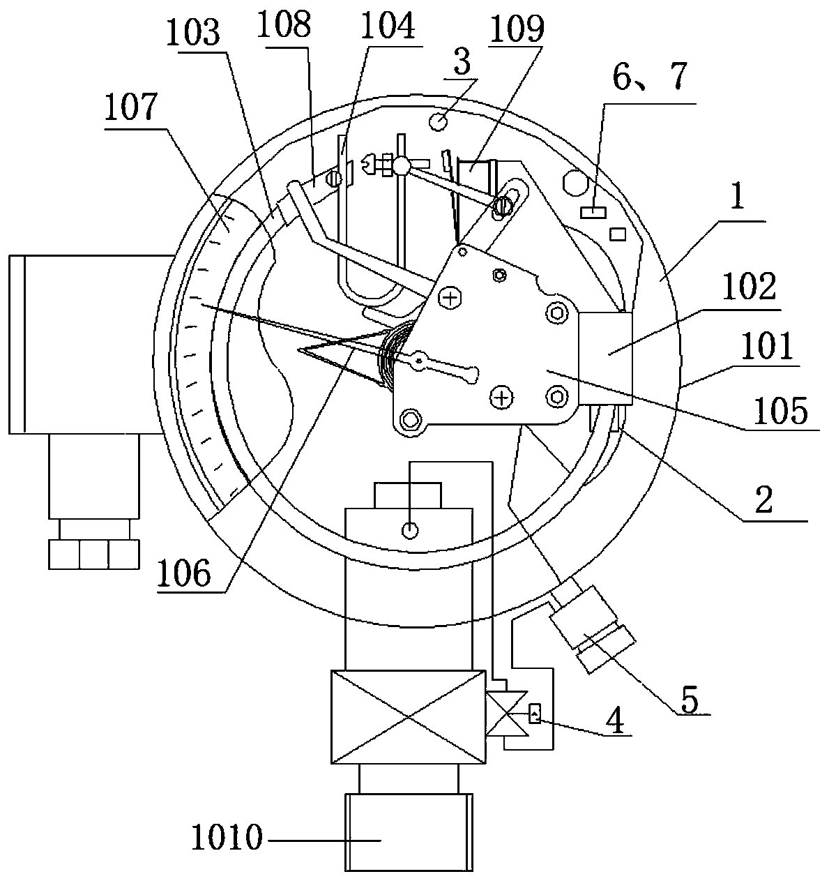
[0197] figure 1 It is a schematic diagram of the structure of a gas density relay. Such as figure 1 As shown, the gas density relay 1 includes: a housing 101, and a base 102, an end seat 108, a pressure detector 103, a temperature compensating element 104, several signal generators 109, and a core 105 arranged in the housing 101 , Pointer 106, Dial 107. One end of the pressure detector 103 is fixed on the base 102 and communicated with it, and the other end of the pressure detector 103 is connected to one end of the temperature compensation element 104 through the end seat 108, the The other end of the temperature compensating element 104 is provided with a crossbeam, and the crossbeam is provided with an adjusting member that pushes the signal generator 109 to make the contacts of the signal generator 109 on or off. The movement 105 is fixed on the base 102; the other end of the temperature compensation element 104 is also connected to the movement 105 through a connecting...
Embodiment 2
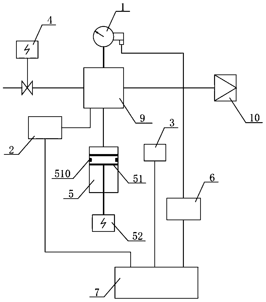
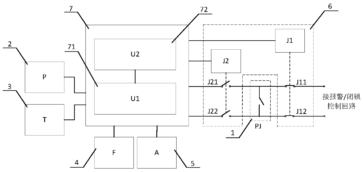
[0226] Such as Figure 4 As shown, a gas density monitoring device includes: a gas density relay 1 (the gas density relay 1 also mainly includes: a housing, and a base, a pressure detector, a temperature compensation element, a movement, and a pointer arranged in the housing. , dial, end seat, several signal generators and electrical equipment connection joints), pressure sensor 2, temperature sensor 3, valve 4, pressure adjustment mechanism 5, online verification contact signal sampling unit 6 and intelligent processor 7.
[0227] The air inlet of the valve 4 is sealed and connected to the electrical equipment through the electrical equipment connecting joint 1010 , and the air outlet of the valve 4 communicates with the base of the gas density relay 1 and the pressure detector. The pressure sensor 2, the temperature sensor 3, the online verification contact signal sampling unit 6, and the intelligent processor 7 are arranged on or in the housing of the gas density relay 1, a...
Embodiment 3
[0235] Such as Figure 5 As shown, a gas density monitoring device, compared with the second embodiment, increases the gas supply interface 10 and the self-sealing valve 11. One end of the self-sealing valve 11 is sealed and connected to electrical equipment, and the other end of the self-sealing valve 11 communicates with the air inlet of the valve 4 and the air supply interface 10 through a connecting pipe.
PUM
 Abstract
Description
Claims
Application Information
 - R&D
- Intellectual Property
- Life Sciences
- Materials
- Tech Scout
- Unparalleled Data Quality
- Higher Quality Content
- 60% Fewer Hallucinations
Browse by: Latest US Patents, China's latest patents, Technical Efficacy Thesaurus, Application Domain, Technology Topic, Popular Technical Reports.
© 2025 PatSnap. All rights reserved.Legal|Privacy policy|Modern Slavery Act Transparency Statement|Sitemap|About US| Contact US: help@patsnap.com


