
Alternating-current sleeve structure

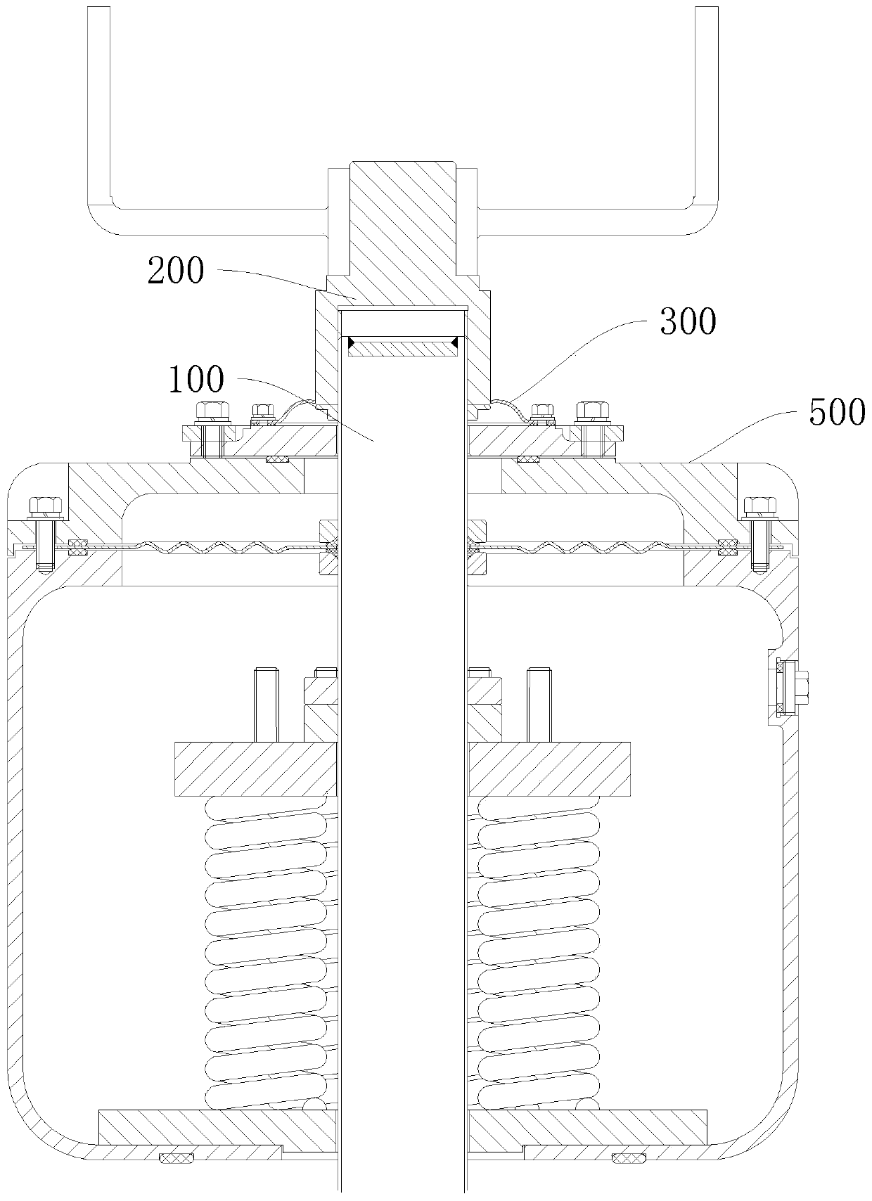
A bushing and conductive tube technology, applied in the direction of screwing one conductor into another conductor, transformer/inductor parts, electrical components, etc., can solve the problem that the displacement can only occur at the top of the cover plate 500 and the contact force of the thread is reduced. , the looseness of the conductive head 200, etc., to avoid the poor contact of the connecting thread and improve the waterproof performance.

Pending Publication Date: 2019-11-12
EXAMING & EXPERIMENTAL CENT OF ULTRAHIGH VOLTAGE POWER TRANSMISSION COMPANY CHINA SOUTHEN POWER GRID
View PDF0 Cites 0 Cited by
  • Summary
  • Abstract
  • Description
  • Claims
  • Application Information

AI Technical Summary

Problems solved by technology

Due to the expansion and contraction of this type of bushing conductive tube 100, the relative displacement with the outer casing of the casing can only occur at the top of the cover plate 500, so the conductive head 200 expands when the temperature of the conductive tube 100 rises (the thermal expansion coefficient of the conductive tube 100 greater than the porcelain piece), there will be a gap between the lower eaves and the transition plate on the cover plate 500, resulting in a decrease in thread contact force and loosening of the conductive head 200

Method used


Image

  • Alternating-current sleeve structure
  • Alternating-current sleeve structure
  • Alternating-current sleeve structure

Examples


Embodiment

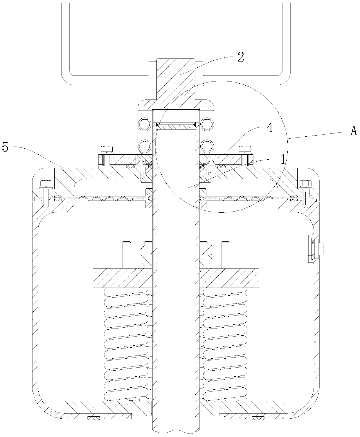
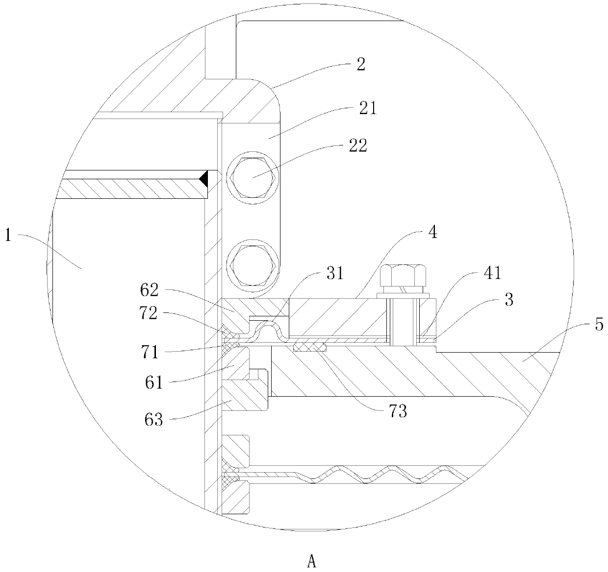
[0020] Such as figure 2 with image 3 As shown, an AC bushing structure includes a conductive tube 1, a conductive head 2 screwed to the head of the conductive tube 1, a cover plate 5, and an elastic plate 3 and a pressure ring 4 sequentially installed above the cover plate 5 to close the The top of the cover plate 5 prevents water from flowing into the inside.

[0021] The conductive head 2 adopts a Huff structure, that is, at the symmetrical place on both sides of the conductive head 2, there are symmetrically arranged slots 21, and the sides of the two slots 21 are provided with through holes through the conductive head 2. There are 2 on the side, 4 in total. When the conductive head 2 is screwed to the conductive pipe 1, the through hole is equipped with a screw 22 and a nut, so that the conductive head 2 clamps the conductive pipe 1, so that the conductive head 2 and the conductive pipe 1 can be connected even when the temperature of the conductive pipe 1 rises. Even ...


PUM


Abstract

The invention discloses an alternating-current sleeve structure. The alternating-current sleeve structure comprises a conductive tube, a conductive head which is in threaded connection with the head of the conductive tube, a cover plate, and an elastic plate and a pressing ring sequentially arranged above the cover plate; the conductive tube extends out of the cover plate; the pressing ring and the elastic plate are in a circular ring shape; an inner ring of the elastic plate is folded towards an outer ring to form a wave structure; the diameter of the inner ring of the elastic plate is consistent with the diameter of the conductive tube; the pressing ring is fixedly connected with the cover plate through a bolt and presses a plane between the outer ring of the elastic plate and the wave structure; symmetric open grooves are formed in the two sides of the conductive head; through holes penetrating through the wall thickness of the conductive head are formed in the side surfaces of theopen grooves; and nuts and screws are arranged on the through holes in a penetrating mode. According to the alternating-current sleeve structure, the conductive head and the conductive tube are lockedthrough the screws and the nuts; the influence of stress of a drainage bus and vibration of a main transformer on the tightness of threaded connection during operation can be eliminated; and poor contact between the conductive head and the conductive tube is avoided.

Description

technical field [0001] The invention relates to high-voltage maintenance equipment technology, in particular to an AC bushing structure. Background technique [0002] Oil-immersed AC bushings are often used as important components of converters, such as figure 1 As shown, its head mainly includes a bushing current-carrying structure as a guide rod current-carrying structure. Its head is a conductive head 200. The conductive head 200 and the conductive tube 100 are screwed to carry current. Plate, sleeve top design The main function of the conductive head 200 is to prevent rainwater and moisture from entering from the top of the sleeve. However, this part of the structure also needs to consider the thermal expansion of the conductive tube. The main function of the original elastic plate 300 is to seal the shaft of the conductive tube 100 at the top of the casing, and to leave a certain margin for thermal expansion and contraction of the conductive tube 100 . Due to the expa...

Claims


Application Information

Patent Timeline
Patent Type & Authority Applications(China)
IPC IPC(8): H01F27/29H01F27/32H01R4/30H01R4/56H01R4/60
CPCH01F27/29H01F27/324H01R4/30H01R4/56H01R4/60
Inventor 韦晓星张晋寅
Owner EXAMING & EXPERIMENTAL CENT OF ULTRAHIGH VOLTAGE POWER TRANSMISSION COMPANY CHINA SOUTHEN POWER GRID
Learn More