
Tilting structure of aircraft and vertical take-off and landing aircraft

A technology for an aircraft and a rotating arm, applied in the field of aircraft, can solve problems such as steering gear wind resistance, and achieve the effects of long service life, high reliability and slender structure

Pending Publication Date: 2019-11-12
SHENZHEN SMART DRONE UAV CO LTD
View PDF0 Cites 5 Cited by
  • Summary
  • Abstract
  • Description
  • Claims
  • Application Information

AI Technical Summary

Problems solved by technology

[0006] One of the objectives of the present invention is to provide a tilting structure of an aircraft, which uses a screw assembly to cooperate with a connecting rod to realize the tilting of the tilting arm, so as to solve the wind resistance problem caused by the steering gear in the prior art

Method used


Image

  • Tilting structure of aircraft and vertical take-off and landing aircraft
  • Tilting structure of aircraft and vertical take-off and landing aircraft
  • Tilting structure of aircraft and vertical take-off and landing aircraft

Examples


Embodiment 1

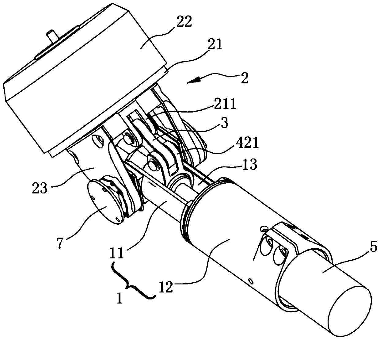
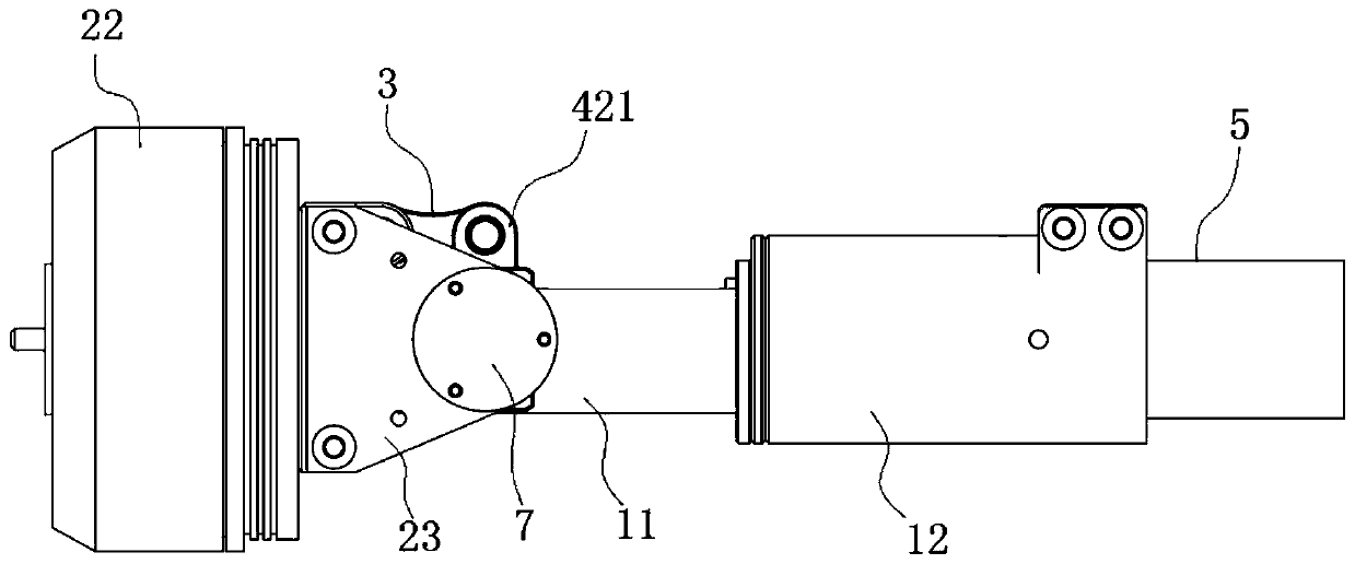
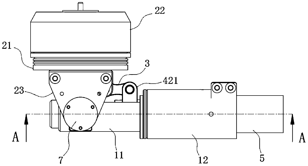
[0039] see Figure 1 to Figure 3 , A preferred embodiment of the present invention discloses a tilting structure of an aircraft, which includes a casing 1, a tilting arm 2, a screw assembly, a connecting rod 3 and a driving device. In normal working condition, the casing 1 is in a horizontal position, and the following descriptions are based on figure 2 As a reference, the left side of the paper is the front of the aircraft, and the right side of the paper is the rear of the aircraft.

[0040] see figure 1 , Figure 4 and Figure 5 , In one of the embodiments, the casing 1 is in the shape of a cylindrical tube, and the casing 1 is in the shape of an elongated strip as a whole. Specifically, the casing 1 is a two-stage structure, which includes a first casing 11 and a second casing 12, and the cross section of the first casing 11 is smaller than the cross section of the second casing 12, the first casing The shaft ends of the body 11 and the second housing 12 are fixedly ...

Embodiment 2

[0063] This embodiment provides a vertical take-off and landing aircraft, which includes a propeller and the tilting structure of the aircraft in the first embodiment.

[0064] In some embodiments, the propeller is installed on the rotating shaft of the power motor 22 .

[0065] Other structures and connections of the vertical take-off and landing aircraft are prior art, and will not be repeated in this embodiment.

[0066] It should be noted that the vertical take-off and landing vehicle may be an unmanned aerial vehicle or other aircraft with a vertical take-off and landing function.

[0067] It can be understood that, in the vertical take-off and landing aircraft of this embodiment, at least one tilting structure is installed, and the tilting structure can be installed at any position of the aircraft. During the vertical take-off and landing of the aircraft, the tilting structure cooperates with the power motor 22 to provide upward power for the aircraft; during the horizo...


PUM


Abstract

The invention discloses a tilting structure of an aircraft and a vertical take-off and landing aircraft, and belongs to the technical field of aircrafts. The tilting structure of the aircraft comprises a shell, a tilting arm, a screw rod assembly, a connecting rod and a driving device, wherein the tilting arm can be pivoted to the shell up and down in a pivoting mode; the screw rod assembly comprises a screw rod and a screw rod nut, and the two ends of the connecting rod are hinged to the tilting arm and the screw rod nut correspondingly; the driving device is connected with the driving end ofthe screw rod and is used for driving the screw rod to rotate; and the driving device drives the screw rod to rotate so as to drive the screw rod nut to slide back and forth, and then pushes the connecting rod to enable the tilting arm to tilt up and down so as to realize the vertical take-off and landing function. According to the titling structure, the screw rod nut is used for transmitting power, so that a whole tilting mechanism has the advantages of being slender and compact in structure, small in pneumatic resistance, high in reliability and long in service life. The invention further provides the vertical take-off and landing aircraft.

Description

technical field [0001] The invention relates to the technical field of aircraft, in particular to a tilting structure of an aircraft and a vertical take-off and landing aircraft. Background technique [0002] The vertical take-off and landing aircraft has the characteristics of both rotary-wing aircraft and fixed-wing aircraft. It does not require a large space for take-off and landing, and the use efficiency of the aircraft is greatly improved when cruising in a horizontal state. [0003] Existing vertical take-off and landing aircraft are mainly divided into compound wing vertical take-off and landing aircraft and tilt rotor vertical take-off and landing aircraft. The compound wing vertical take-off and landing aircraft adopts a set of fixed-wing power system and a set of rotor power system at the same time. The fixed-wing power system is used for fixed-wing cruising state flight, and the rotor power system is used for vertical take-off and landing state flight. The tilt-...

Claims


Application Information

Patent Timeline
IPC IPC(8): B64C27/52B64C27/32B64C29/00
CPCB64C27/52B64C27/32B64C29/00
Inventor 贺剑乐启红
Owner SHENZHEN SMART DRONE UAV CO LTD
Learn More