Welding strip punching device

A welding strip and punching technology, applied in the field of punching welding strip equipment, can solve the problems of reducing the efficiency of large-scale production and processing of welding strips, the welding strip does not have a large-capacity collection operation, and the welding strip does not have multiple production punching holes , to achieve the effect of saving labor time and labor, improving convenience and efficiency, and improving stability and efficiency

Pending Publication Date: 2019-11-12
江苏威腾新材料科技有限公司
View PDF0 Cites 0 Cited by
  • Summary
  • Abstract
  • Description
  • Claims
  • Application Information

AI Technical Summary

Problems solved by technology

[0003] The existing punching ribbon device does not have a stable function when feeding materials, which may easily lead to offset phenomenon when the ribbon is processed, and the ribbon does not have the function of multiple production punching during the punching operation, which reduces the cost of the device. Multi-functionality, impurity particles are likely to be adsorbed on the surface layer of the ribbon during the punching operation of the ribbon, thereby reducing the cleanliness of the device when processing the ribbon. The existing ribbon does not have a large capacity when it is unwinding and rewinding Collecting operation, reducing the efficiency of large-scale production and processing of welding strips

Method used


Image

  • Welding strip punching device
  • Welding strip punching device
  • Welding strip punching device

Examples


Embodiment Construction

[0027] The following will clearly and completely describe the technical solutions in the embodiments of the present invention with reference to the accompanying drawings in the embodiments of the present invention. Obviously, the described embodiments are only some, not all, embodiments of the present invention.

[0028] In the description of the present invention, unless otherwise stated, the meaning of "plurality" is two or more; the terms "upper", "lower", "left", "right", "inner", "outer" , "front end", "rear end", "head", "tail", etc. indicate the orientation or positional relationship based on the orientation or positional relationship shown in the drawings, and are only for the convenience of describing the present invention and simplifying the description, rather than Nothing indicating or implying that a referenced device or element must have a particular orientation, be constructed, and operate in a particular orientation should therefore not be construed as limiting ...


PUM


Abstract

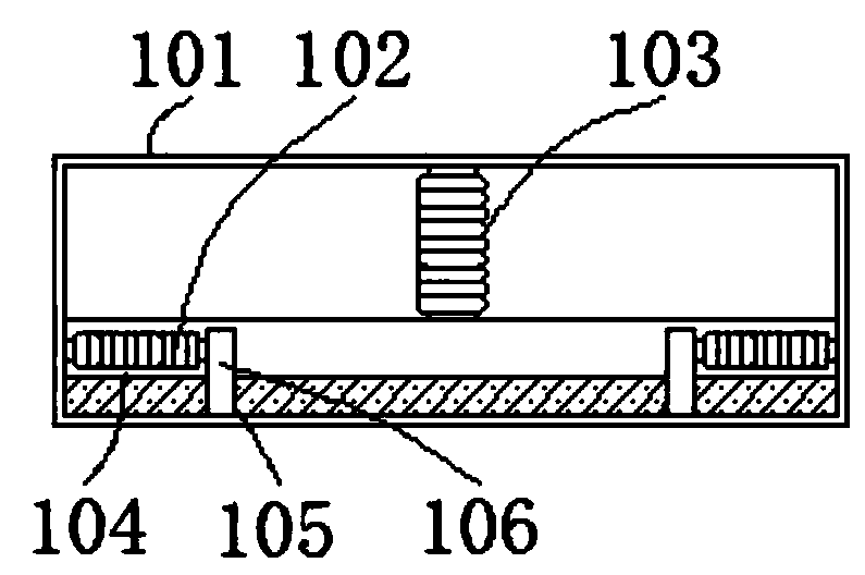
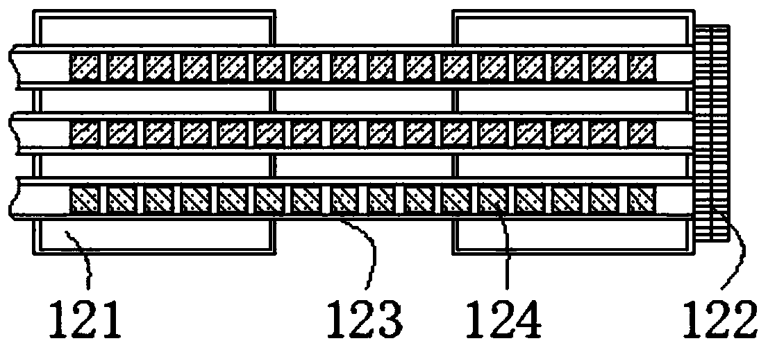
The invention discloses a welding strip punching device and relates to the technical field of welding strip punching equipment. The welding strip punching device comprises an induction control cabinet, wherein the outer side of the induction control cabinet is connected with a receiving wheel, the outer side of the induction control cabinet is provided with a movable mechanism, the outer side of the receiving wheel is connected with a welding strip, the output end of the welding strip is connected with an induction frame, the outer side of the induction frame is provided with an inductor, theouter side of the induction frame is connected with a tightness adjusting wheel, and a guide wheel is mounted on the outer side of the tightness adjusting wheel. The welding strip punching device hasthe beneficial effects that through electrical connection of the induction control cabinet with the inductor, the tightness adjusting wheel, the guide wheel, a linkage device, a high-speed punch press, a feeding mechanism, a hole pitch adjusting device, an auxiliary mechanism, a discharging inductor, an inductor lead, a discharging mechanism, a discharging control box and the like, the device hasan automatic processing and operation function, manual time and labor force are greatly saved, and the device is automatic, multifunctional, convenient to use and efficient.

Description

technical field [0001] The invention relates to the technical field of punching welding strip equipment, in particular to a device for punching welding strip equipment. Background technique [0002] Soldering strips are called tin-plated copper strips or tin-coated copper strips, which are divided into confluence strips and interconnection strips. They are used for the connection between photovoltaic module cells and play an important role in conducting electricity and gathering electricity. The welding strips need to be punched. In the process, it is necessary to transfer the strip-shaped welding strip or the coiled welding strip to the processing position through the conveying device in the punching device for processing. [0003] The existing punching ribbon device does not have a stable function when feeding materials, which may easily lead to offset phenomenon when the ribbon is processed, and the ribbon does not have the function of multiple production punching during ...

Claims


Application Information

Patent Timeline
IPC IPC(8): B21D28/26B21D43/00B21C47/18B21C47/30B08B1/02
CPCB21D28/26B21D43/00B21C47/18B21C47/30B08B1/12B08B1/20
Inventor 陆俊王明松季成洋
Owner 江苏威腾新材料科技有限公司
Why Eureka
Try Eureka