An angle-adjustable laser cleaning machine handheld terminal

A technology of laser cleaning and angle adjustment, used in the field of laser cleaning machines, can solve the problems of high laser directivity and inability to clean

Active Publication Date: 2021-04-27
SHANDONG ZHONGSHI YITONG GRP +1
View PDF8 Cites 0 Cited by
  • Summary
  • Abstract
  • Description
  • Claims
  • Application Information

AI Technical Summary

Problems solved by technology

[0005] For the existing hand-held terminal cleaning device, due to the high directivity of the laser, it can only clean the front of the fixed equipment. For some fixed equipment, the side and back of the workpiece to be cleaned, especially the surface of the workpiece to be cleaned that is difficult for operators to enter cannot be cleaned. Insufficient, the present invention provides an angle-adjustable laser cleaning machine handheld terminal, which can be used for the side and back of the workpiece to be cleaned for some fixed equipment, and is lightweight

Method used


Image

  • An angle-adjustable laser cleaning machine handheld terminal
  • An angle-adjustable laser cleaning machine handheld terminal

Examples


Embodiment 1

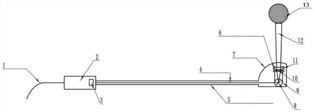
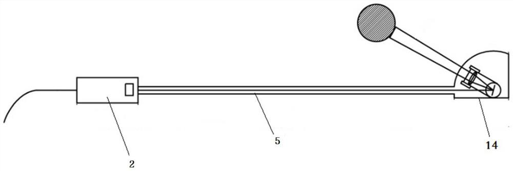
[0045] Such as Figure 1~2As shown, this embodiment discloses an angle-adjustable handheld terminal of a laser cleaning machine, including an external housing mechanism composed of a handheld part 2, a laser beam channel 5, and an accommodating part 14, and the external housing mechanism is used to cover The laser processing mechanism located inside it, the hand-held part 2 is connected with the housing part 14 at the other end through the laser beam channel 5, the laser beam channel 5 can change its length, and the surface of the housing part 14 is provided with an arc-shaped window protection mirror; laser processing The mechanism includes the oscillating mirror 8 and the focusing mirror 10 placed in the accommodating part 14 , the angles of the galvanizing mirror 8 and the focusing mirror 10 are adjustable; it also includes an observing mechanism placed in the accommodating part 14 .

[0046] In order to realize the function of changing the length, the laser beam channel 5 ...

Embodiment 2

[0057] The difference between Embodiment 2 and Embodiment 1 is that in Embodiment 2, the observation mechanism further includes a camera 11 disposed in the accommodating portion 14 for observing the surface of the workpiece 13 to be cleaned, and the camera 11 is installed on the focusing lens 10 . Used to observe the workpiece to be cleaned and the cleaning indicator line.

[0058] A controller is arranged in the hand-held part 2, and the controller is connected with the laser output head, the vibrating mirror 8, the laser range finder, the cleaning indicator line emission mechanism and the camera 11.

[0059] A jog switch 3 is also installed on the outside of the handle 2, and the jog switch 3 is connected to the controller.

[0060] It also includes a control panel for parameter setting and display, and the control panel is connected with the controller and the observation mechanism.

[0061] Embodiment 2 is different from Embodiment 1 in the working mode. Specifically, in ...


PUM


Abstract

The invention discloses an angle-adjustable handheld terminal of a laser cleaning machine, which can be used for the side and back of workpieces to be cleaned for some fixed equipment, and has excellent physical properties, including an optical fiber collimation system for transmitting laser light, which It has a shell, and the shell can be used as a hand-held part; the retractable laser beam channel, the galvanometer and the focusing mirror with adjustable angles, the hand-held part is connected to the accommodation part at the other end through the laser beam channel, and the surface of the accommodation part is protected by an arc window mirror, the vibrating mirror and focusing mirror are placed in the accommodating part; the vibrating mirror and focusing mirror in the accommodating part can be manually or electrically adjusted in angle; wherein, the adjusting angle of the focusing mirror is twice the adjusting angle of the vibrating mirror.

Description

technical field [0001] The present invention relates to the field of laser cleaning machines, in particular to an angle-adjustable handheld terminal for laser cleaning machines. Background technique [0002] Laser cleaning is mainly based on the substrate surface pollutants (paint, rust, etc.) absorbing laser energy, or vaporization volatilization, or instantaneous thermal expansion to overcome the adsorption force of the surface to the particles, so that they are separated from the surface of the object, and then achieve the purpose of cleaning . Its physical principle can be summarized as follows: a) the beam emitted by the laser is absorbed by the pollution layer on the surface to be treated; b) the absorption of large energy forms a rapidly expanding plasma (highly ionized unstable gas), generating shock waves; c) The shock wave fragments and removes the contaminants; where the light pulse width must be short enough to avoid heat build-up that damages the surface being ...

Claims


Application Information

Patent Timeline
Patent Type & Authority Patents(China)
IPC IPC(8): B08B7/00B08B13/00
CPCB08B7/0042B08B13/00
Inventor 朱慧敏张都清张秉良杨莉莉马勇韩梁郭锐
Owner SHANDONG ZHONGSHI YITONG GRP
Why Eureka
Try Eureka