Adjustable dental pad
An adjustable, tooth pad technology, applied in the field of medical devices, can solve problems such as biting yourself
- Summary
- Abstract
- Description
- Claims
- Application Information
AI Technical Summary
Problems solved by technology
Method used
Image

Examples
Embodiment 1
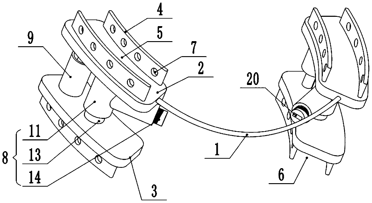
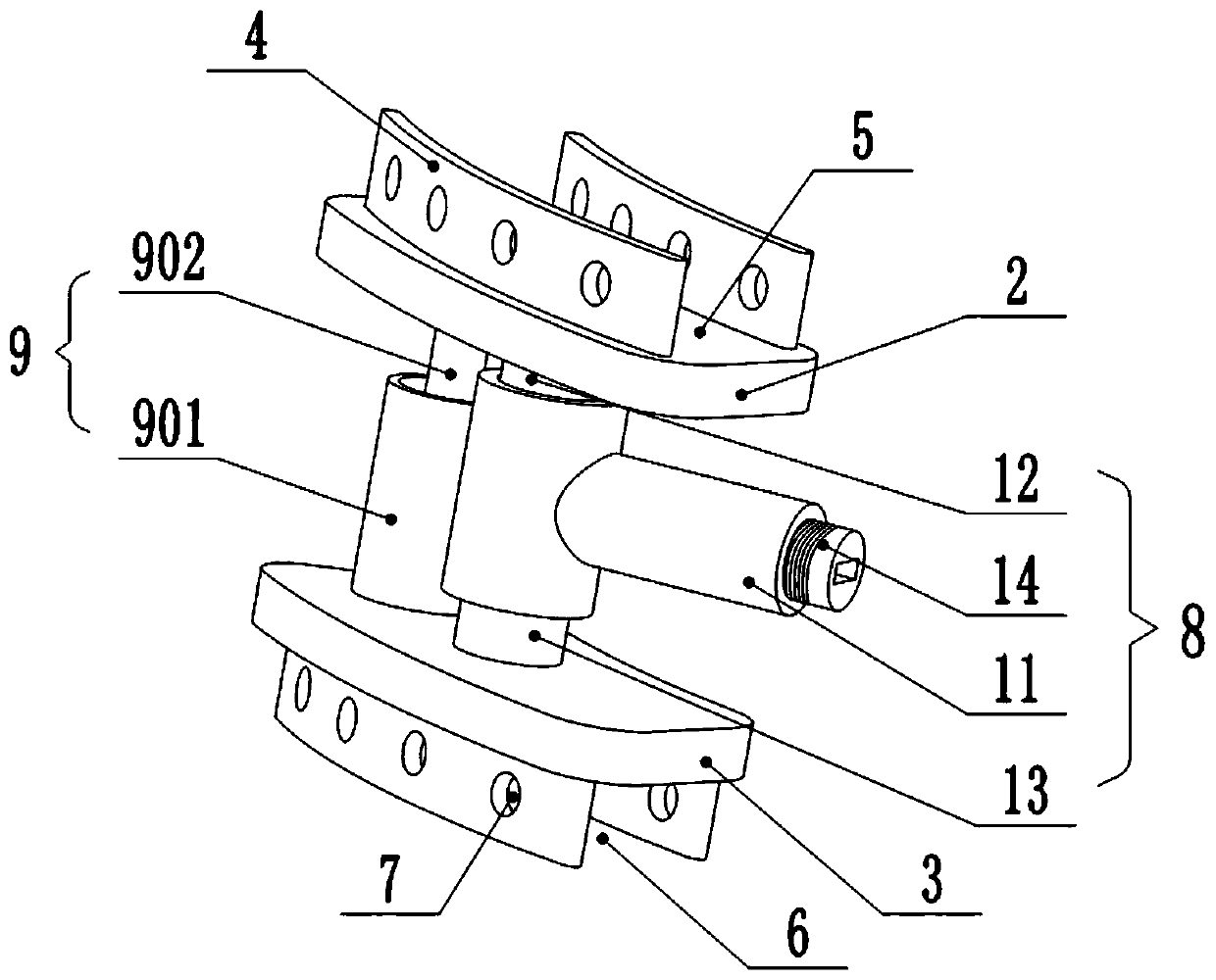
[0037] This embodiment is basically as figure 1 , figure 2 , image 3 with Figure 4 Shown: an adjustable dental pad, including two groups of dental pad bodies, an elastic connector 1 is arranged between the two groups of dental pad bodies, each group of dental pad bodies includes an upper dental pad 2 and a lower dental pad 3, and elastic connectors The two ends of 1 are respectively connected with the upper dental pads 2 of the two groups of dental pad bodies.
[0038] The upper surface of the upper dental pad 2 and the lower surface of the lower dental pad 3 are fixedly connected with an elastic silicone layer, and the upper surface of the upper dental pad 2 and the lower surface of the lower dental pad 3 are fixedly connected with two opposite side plates 4 , the two side plates 4 and the upper tooth pad 2 form the upper alveolar 5 for accommodating the teeth, and the two side plates 4 and the lower tooth pad 3 form the lower alveolar 6 for accommodating the teeth; the...
Embodiment 2
[0049] The difference between this embodiment and Embodiment 1 is that: Figure 5 As shown, in this embodiment, the way in which the top of the upper strut 12 is movably connected to the upper dental pad 2 is different from that of Embodiment 1. Specifically, the top of the upper strut 12 is integrally formed with a support shaft 22, and the top of the support shaft 22 A cylinder 23 is fixedly connected, and the outer periphery of the cylinder 23 is provided with a cylinder 24 , the outer peripheral wall of the cylinder 24 is fixedly connected with a connecting rod 25 , and the top end of the connecting rod 25 is fixedly connected with the upper tooth pad 2 .
[0050] In this embodiment, the cylinder 23 is rotatably connected to the cylinder 24, so as to realize the flexible connection between the upper support column 12 and the upper dental pad 2, and the upper dental pad 2 can rotate to adapt to the opening angle of the patient's mouth.
Embodiment 3
[0052] The difference between this embodiment and Embodiment 1 is that: Image 6 As shown, in this embodiment, the way in which the top of the upper strut 12 is movably connected to the upper tooth pad 2 is different from that of Embodiment 1. Specifically, the top of the upper strut 12 is fixedly connected with a ball sleeve 26, and the top of the ball sleeve 26 Opening, a ball 27 is placed in the ball sleeve 26, and the top of the ball 27 is fixedly connected with the upper teeth pad 2. In addition, the upper side of the lower tooth pad 3 is provided with a groove for placing the bottom end of the lower support column 13 , and the groove fits with the bottom end of the lower support column 13 so that the lower support column 13 can rotate relative to the lower dental pad 3 . In addition, the right end of the horizontal cylinder 112 in the adjustment unit 8 and the right end of the adjustment column 14 are all rounded, that is, the right end of the horizontal cylinder 112 and...
PUM
 Abstract
Description
Claims
Application Information
 - R&D
- Intellectual Property
- Life Sciences
- Materials
- Tech Scout
- Unparalleled Data Quality
- Higher Quality Content
- 60% Fewer Hallucinations
Browse by: Latest US Patents, China's latest patents, Technical Efficacy Thesaurus, Application Domain, Technology Topic, Popular Technical Reports.
© 2025 PatSnap. All rights reserved.Legal|Privacy policy|Modern Slavery Act Transparency Statement|Sitemap|About US| Contact US: help@patsnap.com