Two-wire type magnetic proximity switch
A magnetic proximity switch, wire-type technology, applied in electronic switches, electrical components, pulse technology, etc., can solve the problems of short life of magnetic proximity switches
- Summary
- Abstract
- Description
- Claims
- Application Information
AI Technical Summary
Problems solved by technology
Method used
Image


Examples
Embodiment 1
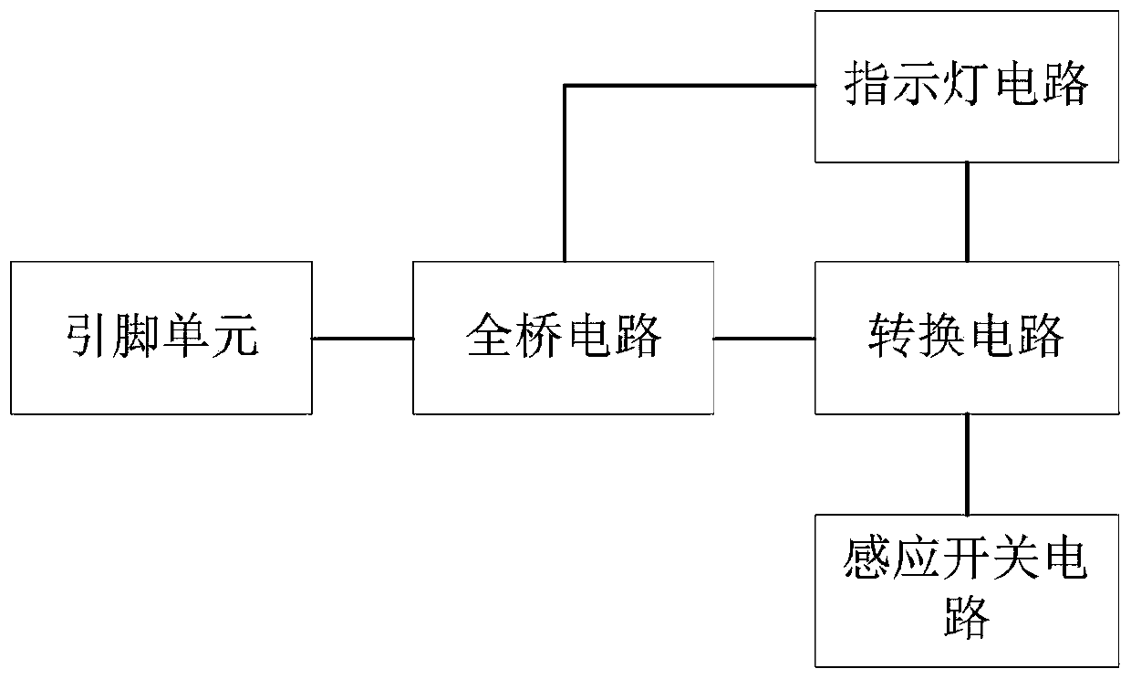
[0025] A two-wire magnetic proximity switch, including a housing and a switch circuit arranged in the housing, the structure of the switch circuit is as follows Figure 1-Figure 2 shown, including:
[0026] a pin unit, including a first pin and a second pin;
[0027] Full bridge circuit, the full bridge circuit is connected to the output terminal of the pin unit, which is used to ensure the non-polarity of the pin unit,
[0028] Since ordinary magnetic proximity switches need to pay attention to the positive and negative of the pins when using them, if the wrong pins are connected, the switch will be unusable. Therefore, in the embodiment of the present invention, a The full bridge circuit V is used to ensure that the two pins can be used interchangeably, so that the two pins have no polarity, so as to prevent the circuit from being unusable due to wrong pin connection when the user is using it.
[0029] A conversion circuit, the conversion circuit is connected to the output...
Embodiment 2
[0036] A two-wire magnetic proximity switch, including a housing and a switch circuit arranged in the housing, the structure of the switch circuit is as follows image 3 shown, including:
[0037] a pin unit, including a first pin and a second pin;
[0038] A full-bridge circuit, the full-bridge circuit is connected to the output terminal of the pin unit to ensure the non-polarity of the pin unit;
[0039] A conversion circuit, the conversion circuit is connected to the output terminal of the full bridge circuit and the induction switch, and is used to convert the normally open state or the normally closed state of the switch circuit according to the induction switch;
[0040] The indicator light circuit, the indicator light circuit is connected to the conversion circuit, and is used to display the working state of the switch circuit. In an embodiment of the present invention, the indicator light circuit includes a light emitting diode D;
[0041] The inductive switch circui...
Embodiment 3
[0048] A two-wire magnetic proximity switch such as Figure 4As shown, it includes a housing and a switch circuit arranged in the housing. In an embodiment of the present invention, the housing includes a main housing 1 provided with a cavity, and the switching circuit is installed in the cavity of the main housing 1. The main housing The lower side of the housing 1 is provided with a pin hole, and the first pin 2 and the second pin 2 in the switch circuit respectively pass through the pin hole and are fixed. The upper side of the main housing 1 is detachably provided with an upper cover, and The cover includes a mounting plate 3 and a waterproof portion 4 arranged on the mounting plate 3. The mounting plate 3 is symmetrically provided with mounting holes 5, and the two-wire magnetic proximity switch of the present invention can be fixed by passing through the mounting holes 5 with screws.
[0049] In the embodiment of the present invention, the waterproof part 4 has a cubic s...
PUM
 Abstract
Description
Claims
Application Information
 - R&D
- Intellectual Property
- Life Sciences
- Materials
- Tech Scout
- Unparalleled Data Quality
- Higher Quality Content
- 60% Fewer Hallucinations
Browse by: Latest US Patents, China's latest patents, Technical Efficacy Thesaurus, Application Domain, Technology Topic, Popular Technical Reports.
© 2025 PatSnap. All rights reserved.Legal|Privacy policy|Modern Slavery Act Transparency Statement|Sitemap|About US| Contact US: help@patsnap.com