
Display panel and display device

A technology for display panels and color filter substrates, which is applied to instruments, computing, optics, etc., can solve the problems of low luminous brightness of display panels and emission of display panels, and achieve the effect of improving luminous brightness and reducing the degree of occlusion

Active Publication Date: 2022-02-22
XIAMEN TIANMA MICRO ELECTRONICS
View PDF0 Cites 0 Cited by
  • Summary
  • Abstract
  • Description
  • Claims
  • Application Information

AI Technical Summary

Problems solved by technology

However, part of the light transmitted from the color-resist layer will be blocked by the light-shielding layer and cannot be emitted from the light-emitting side of the display panel, resulting in a relatively low luminance of the display panel.

Method used


Image

  • Display panel and display device
  • Display panel and display device
  • Display panel and display device

Examples


Embodiment Construction

[0020] The present invention will be further described in detail below in conjunction with the accompanying drawings and embodiments. It should be understood that the specific embodiments described here are only used to explain the present invention, but not to limit the present invention. In addition, it should be noted that, for the convenience of description, only some structures related to the present invention are shown in the drawings but not all structures.

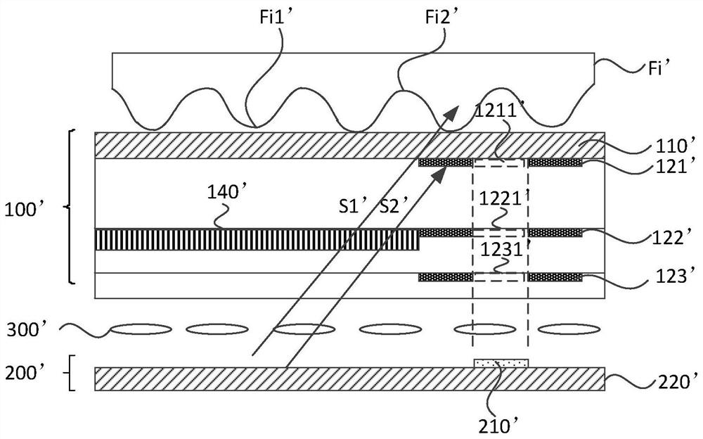
[0021] figure 1 It is a structural schematic diagram of a display panel provided by the prior art. see figure 1 , the display panel includes a color filter substrate 100' and an array substrate 200' disposed opposite to each other, and a liquid crystal layer 300' is arranged between the color filter substrate 100' and the array substrate 200'. The array substrate 200' includes a second base substrate 220' and a plurality of photosensitive units 210' located on the side of the second base substrate 220' facing th...


PUM


Abstract

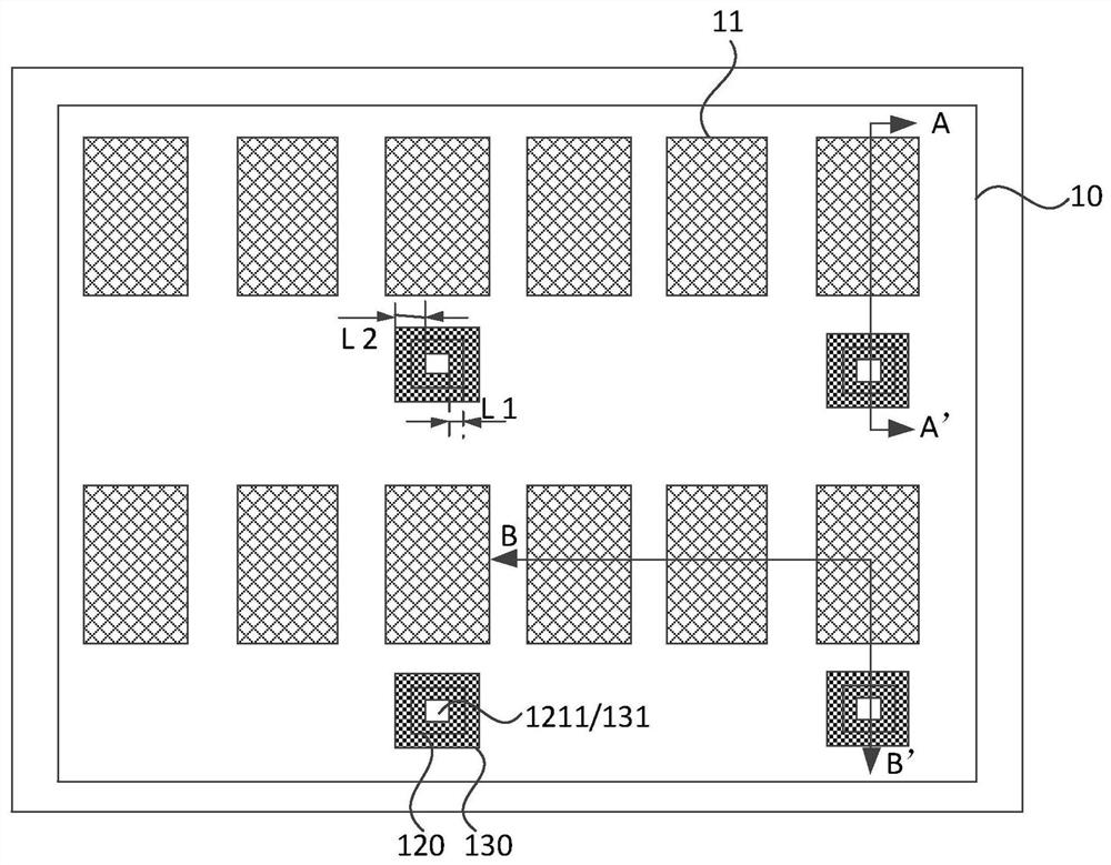
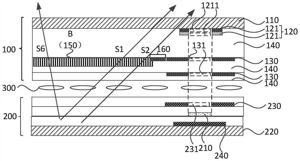
The embodiment of the invention discloses a display panel and a display device. It includes a color filter substrate and an array substrate, the array substrate includes a plurality of photosensitive units; the color filter substrate includes a first base substrate, a first light-shielding layer and at least one second light-shielding layer sequentially arranged toward the side of the array substrate; the first light-shielding layer The layer includes at least two sub-light-shielding layers, each sub-light-shielding layer is provided with a first opening; each second light-shielding layer is provided with a second opening; the first opening, the second opening and the photosensitive unit are on the first base substrate The vertical projections of are at least partially coincident; the maximum distance between the edge of the first shading layer and the edge of the first opening is L 1 ; The maximum distance between the edge of the second light-shielding layer and the edge of the second opening of the second light-shielding layer is L 2 ; L 1 <l2. The thickness of the first light-shielding layer is greater than the thickness of any second light-shielding layer. The technical solutions provided by the embodiments of the present invention can reduce the shielding degree of the outgoing light by the first light-shielding layer, and improve the luminance of the display panel.< / l

Description

technical field [0001] Embodiments of the present invention relate to the field of display technology, and in particular, to a display panel and a display device. Background technique [0002] At present, in-screen fingerprint recognition, that is, embedding the fingerprint recognition unit in the display area, is a hotspot in the current display field research, which is conducive to improving the screen-to-body ratio of the display. [0003] Existing fingerprint identification technologies include optical fingerprint identification technology, semiconductor silicon fingerprint identification technology and ultrasonic fingerprint identification technology. Among them, the optical fingerprint recognition technology generally uses a photodiode as the light-sensing unit. Its working principle is: the reflected light formed after the light is reflected by the touch body is irradiated on the photodiode, so that the photodiode generates a photocurrent. There is a difference in th...

Claims


Application Information

Patent Timeline
Patent Type & Authority Patents(China)
IPC IPC(8): G02F1/1335G06V40/13
CPCG02F1/133512G06V40/13
Inventor 凌安恺沈柏平
Owner XIAMEN TIANMA MICRO ELECTRONICS
Learn More