Relative laser thickness gauge

A laser thickness measurement and thickness gauge technology, applied in the field of optical measurement, can solve problems such as collision, warpage of measurement parts, measurement errors, etc., to achieve accurate measurement accuracy and improve measurement accuracy.

Pending Publication Date: 2019-11-08
宾努克斯科技(佛山)有限公司
View PDF0 Cites 4 Cited by
  • Summary
  • Abstract
  • Description
  • Claims
  • Application Information

AI Technical Summary

Problems solved by technology

[0002] The traditional contact thickness gauge needs the measuring instrument to be in contact with the part. The contact dotting is easy to cause collision, and it is difficult to ensure uniform dotting force, which is easy to cause measurement errors.
The existing single laser dotting is mainly based on the working surface, but if the working surface is uneven or the contact surface of the measuring piece is warped, the measurement result will be directly imaged.

Method used


Image

  • Relative laser thickness gauge
  • Relative laser thickness gauge
  • Relative laser thickness gauge

Examples


Embodiment Construction

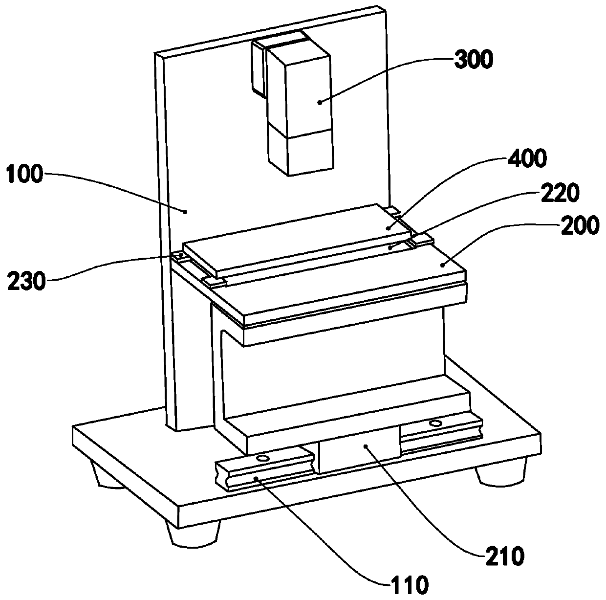
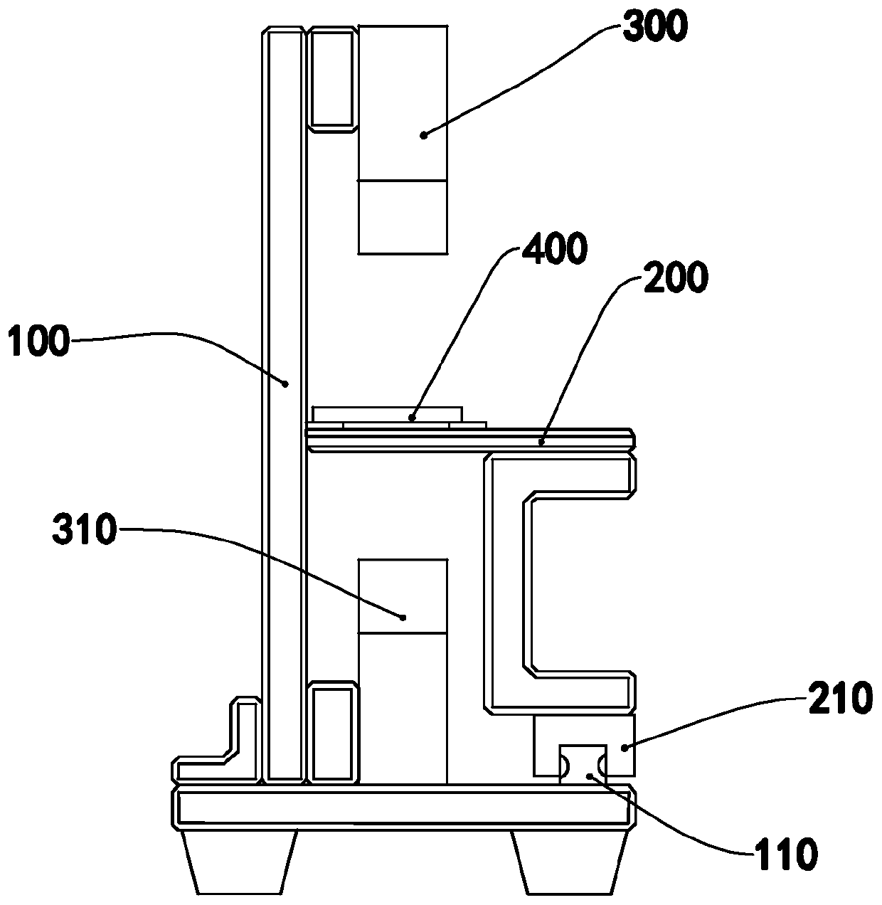
[0021] Such as Figure 1 to Figure 2 As shown, the relative laser thickness gauge of this embodiment includes a bracket 100 , a workbench 200 and two white light confocal displacement sensors 300 .

[0022] The support 100 is provided with a guide rail 110 extending on a horizontal plane, and the workbench 200 is connected with a slider 210 . The slider 210 cooperates with the guide rail 110 so that the workbench 200 can move along the guide rail 110 . The workbench 200 has a measuring piece placement area for placing the measuring piece 400 , a notch 220 is provided in the measuring piece placement area, and a backing plate 230 is provided around the notch 220 , and the backing plate 230 is used for placing the measuring piece 400 . The upper surface of the backing plate 230 can be used as a reference plane for thickness measurement.

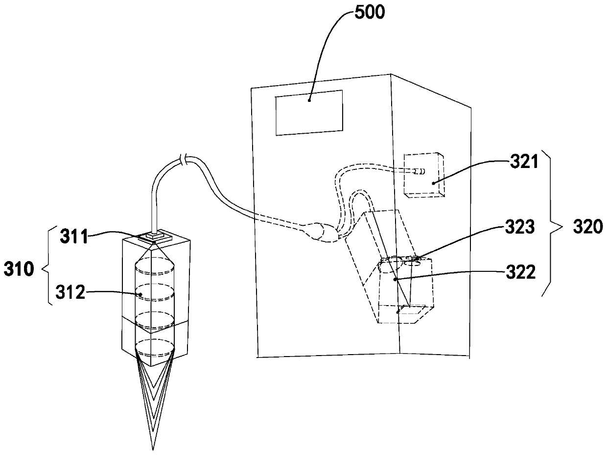
[0023] Such as image 3 As shown, each white light confocal displacement sensor 300 includes a laser side head 310 , a processing device 320...


PUM


Abstract

The invention relates to a relative laser thickness gauge. The relative laser thickness gauge comprises a workbench, wherein the workbench is provided with a measuring piece placing area used for containing a measuring piece, and the measuring piece placing area is provided with a notch. The relative laser thickness gauge further comprises two white light confocal displacement sensors, each whitelight confocal displacement sensor comprises a laser measuring head, and the two laser measuring heads of the two white light confocal displacement sensors are opposite to each other and are vertically arranged on the two sides of the notch respectively. Thickness measurement of a part is not based on the surface of workbench, and the measuring result is not affected by the uneven surface of workbench or warping of the surface of the part. The relative laser thickness gauge can greatly improve the thickness measuring precision.

Description

technical field [0001] The invention relates to the technical field of optical measurement, in particular to a relative laser thickness gauge. Background technique [0002] The traditional contact thickness gauge requires the measuring instrument to be in contact with the part. The contact dotting is easy to cause collision, and it is difficult to ensure uniform dotting force, which may easily cause measurement errors. The existing single laser marking is mainly based on the worktable, but if the worktable is uneven or the contact surface of the measuring part is warped, the measurement result will be directly imaged. Contents of the invention [0003] Aiming at the deficiencies of the prior art, the object of the present invention is to provide a relative laser thickness gauge capable of improving measurement accuracy. [0004] To achieve the purpose of the present invention, the present invention provides a relative laser thickness gauge, including a workbench, the work...

Claims


Application Information

Patent Timeline
Patent Type & Authority Applications(China)
IPC IPC(8): G01B11/06
CPCG01B11/06
Inventor 王和云
Owner 宾努克斯科技(佛山)有限公司
Why Eureka
Try Eureka