
Automatic pressure regulating diaphragm pump

A technology of automatic pressure regulation and diaphragm pump, which is applied in the direction of pumps, pump control, machines/engines, etc. It can solve the problems of unable to adjust the internal working pressure, stop working of the diaphragm pump, overload the motor, etc., and achieve flexible and changeable use scenarios , avoid motor damage, increase the effect of torque output

Pending Publication Date: 2019-11-08
王建设
View PDF0 Cites 1 Cited by
  • Summary
  • Abstract
  • Description
  • Claims
  • Application Information

AI Technical Summary

Problems solved by technology

[0002] The diaphragm pump is driven by a motor. When the water output is reduced, the motor load will also increase; therefore, the decrease in the water output may cause the motor to overload, causing the piston to stop moving and the diaphragm pump to stop working.
Therefore, the existing diaphragm pump is provided with a pressure relief valve to relieve the pressure when the pressure in the pump body is too high, and the internal working pressure cannot be adjusted.

Method used


Image

  • Automatic pressure regulating diaphragm pump
  • Automatic pressure regulating diaphragm pump
  • Automatic pressure regulating diaphragm pump

Examples


Embodiment Construction

[0050] Embodiments of the present invention are described in detail below, examples of which are shown in the drawings, wherein the same or similar reference numerals designate the same or similar elements or elements having the same or similar functions throughout. The embodiments described below by referring to the figures are exemplary and are intended to explain the present invention and should not be construed as limiting the present invention.

[0051] In describing the present invention, it should be understood that the terms "length", "width", "upper", "lower", "front", "rear", "left", "right", "vertical", The orientation or positional relationship indicated by "horizontal", "top", "bottom", "inner", "outer", etc. are based on the orientation or positional relationship shown in the drawings, and are only for the convenience of describing the present invention and simplifying the description, rather than Nothing indicating or implying that a referenced device or element...


PUM


Abstract

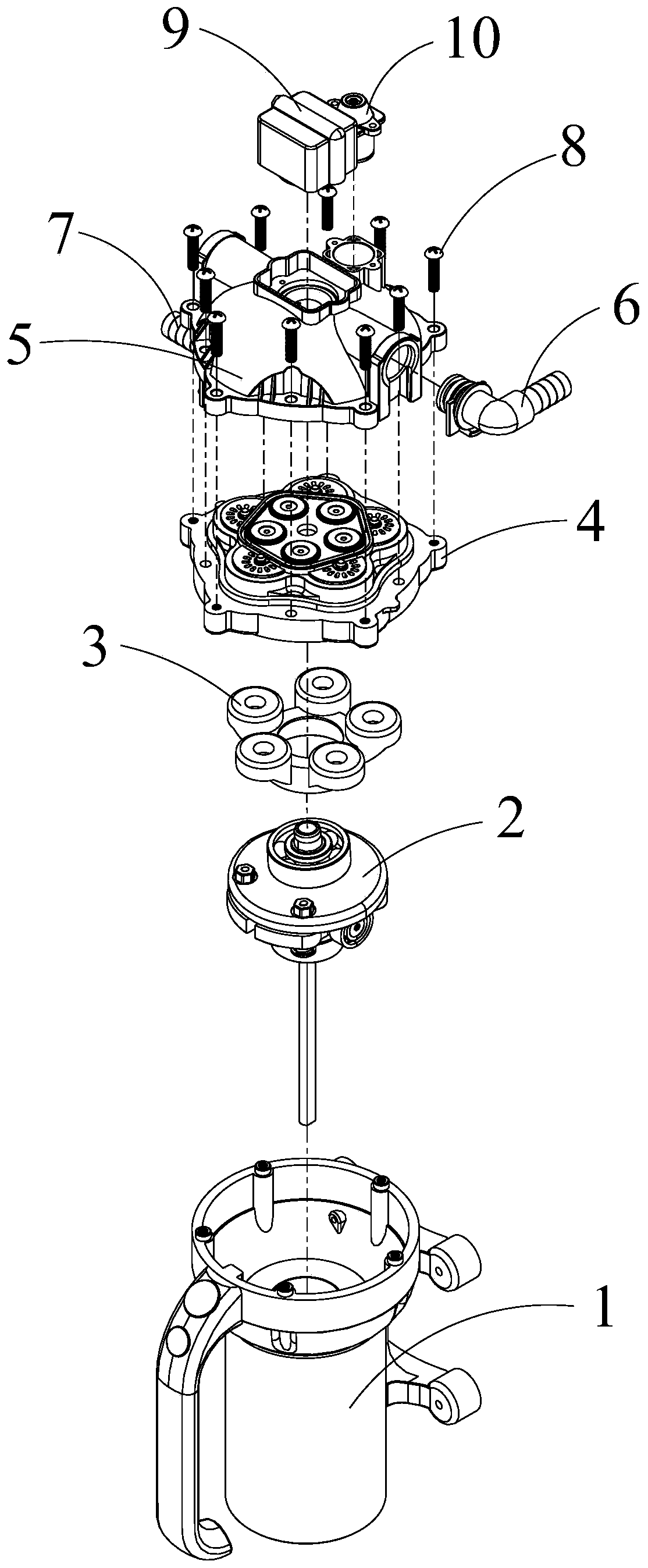
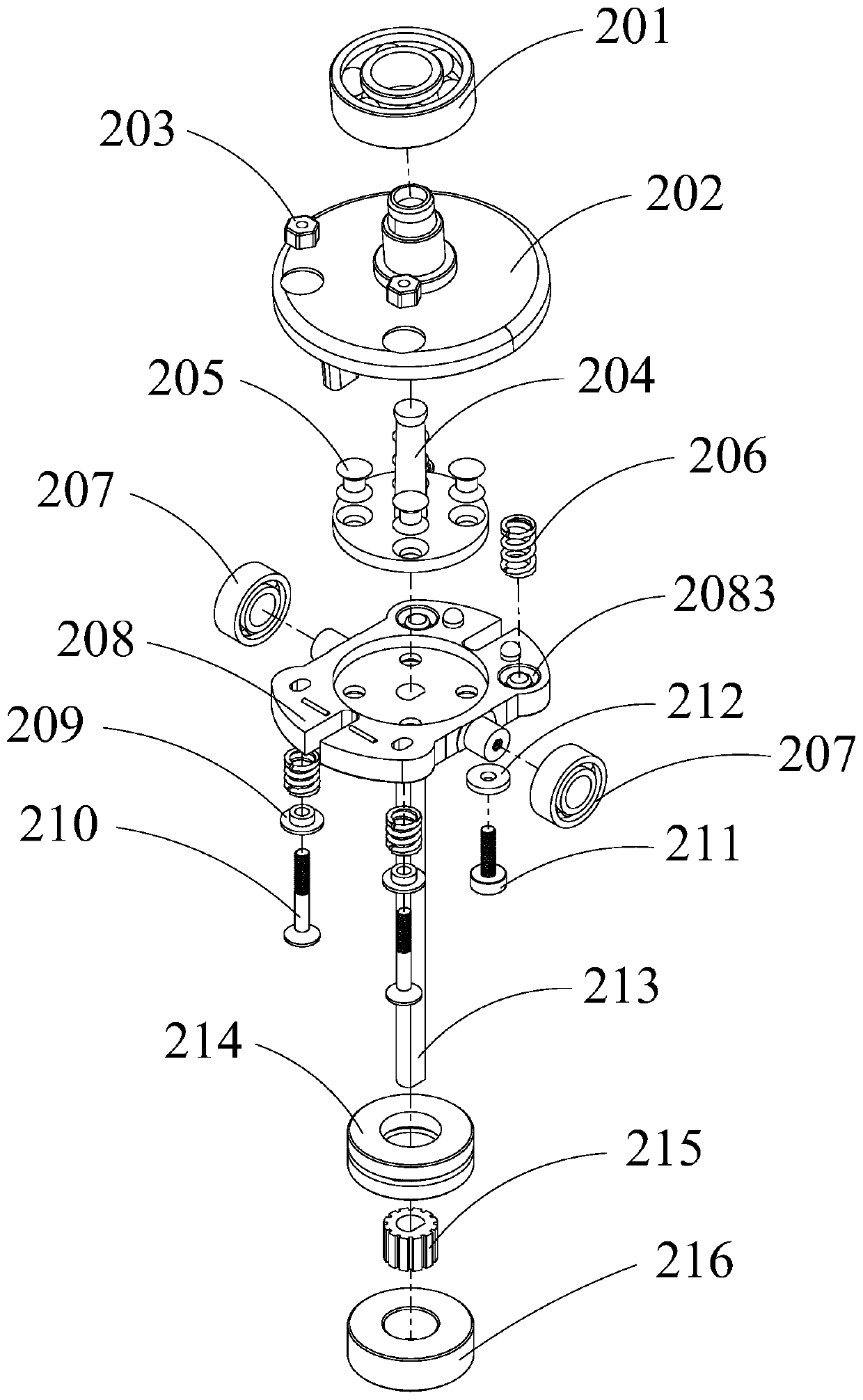
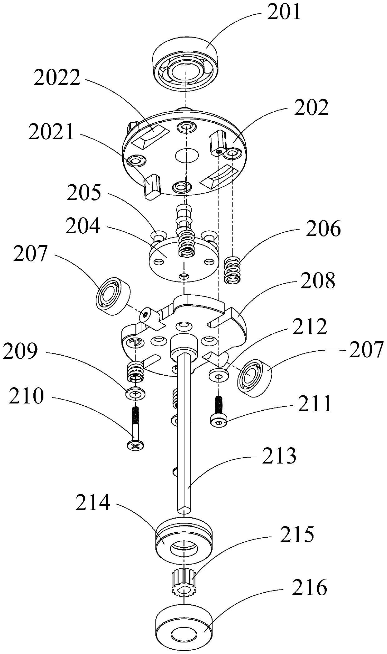
The invention provides an automatic pressure regulating diaphragm pump. The automatic pressure regulating diaphragm pump comprises a shell, a pump core, a diaphragm connecting seat and a pump body, wherein the pump core comprises a stress swinging bracket, a concentric positioning shaft and a pressure regulating base, the concentric positioning shaft is fixed to the pressure regulating base and isused for guaranteeing the concentricity of the stress swinging bracket when pressure is automatically regulated and preventing a diaphragm from being damaged, and the stress swinging bracket sleevesthe concentric positioning shaft and is pressed by a pressure spring so as to form a certain included angle together with the pressure regulating base. According to the automatic pressure regulating diaphragm pump, a piston moves up and down by using the height difference of both ends generated when the stress swinging bracket which is put in an inclined mode rotates, so that a supercharging effect is achieved, and the maximum water yield under the effect of initial pressure is reached; the included angle of the stress swinging bracket is reduced by using the principle that the pressure of thepiston is increased so as to force the spring to retract when the water yield is low, so that the piston stroke is shortened, the torque output is increased in the condition that motor power is not changed, and a motor is prevented from being damaged while the water outlet pressure is increased.

Description

technical field [0001] The invention relates to a diaphragm pump, in particular to an automatic pressure-regulating diaphragm pump. Background technique [0002] The diaphragm pump is driven by a motor. When the water output is reduced, the motor load will also increase; therefore, the decrease in water output may cause the motor to overload, causing the piston to stop moving and the diaphragm pump to stop working. Therefore, the existing diaphragm pump is provided with a pressure relief valve to relieve the pressure when the pressure in the pump body is too high, so that the internal working pressure cannot be adjusted. Contents of the invention [0003] (1) Technical problems to be solved [0004] The purpose of the present invention is to provide an automatic pressure-regulating diaphragm pump, which has the function of automatically adjusting the piston stroke according to the working load, and realizes the automatic pressure-regulating function of the diaphragm pump....

Claims


Application Information

Patent Timeline
Patent Type & Authority Applications(China)
IPC IPC(8): F04B43/04F04B49/12
CPCF04B43/04F04B43/0081F04B49/12
Inventor 王建设王恒聪
Owner 王建设
Learn More