Presser foot driving assembly with stable driving and embroidery machine

A technology of driving components and driving parts, which is applied in the field of embroidery machines, can solve problems such as loud noise, affecting embroidery quality, and generating vibration, and achieve the effects of reducing noise, improving embroidery quality, and facilitating fitting and disengagement

Pending Publication Date: 2019-11-08
ZHEJIANG XINSHENG SEWING EQUIP
View PDF0 Cites 2 Cited by
  • Summary
  • Abstract
  • Description
  • Claims
  • Application Information

AI Technical Summary

Problems solved by technology

[0002] The currently used embroidery machine presser foot driving structure can refer to figure 1 As shown, it includes a presser foot 22 and a presser foot driver 11. The presser foot 22 has a sliding sleeve 221 slidably installed on the needle bar 22. The needle bar 22 is connected with a needle bar driving sleeve 211. The needle bar driver 12 and the presser foot driver 11 slide Installed on the fixed shaft 13, a presser foot spring 223 is provided between the needle bar driving sleeve 211 and the sliding sleeve 221, the presser foot driver 11 includes a driving part, and the driving part has a protruding part 110, and the protruding part is located below the sliding sleeve 221, so that When the needle bar driver 12 drives the needle bar driving sleeve 211 to drive the needle bar 21 to move down, the presser foot 22 also moves down, and at the same time the presser foot driver 11 also moves down. When the protruding part 110 touches, it will produce impact, not only the noise is large, but also vibration will be generated, which affects the quality of embroidery

Method used


Image

  • Presser foot driving assembly with stable driving and embroidery machine
  • Presser foot driving assembly with stable driving and embroidery machine
  • Presser foot driving assembly with stable driving and embroidery machine

Examples


Embodiment 1

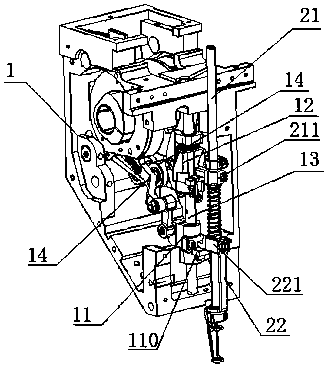
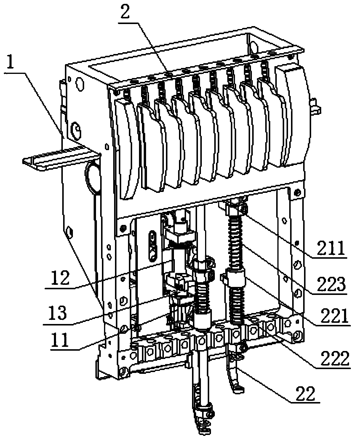
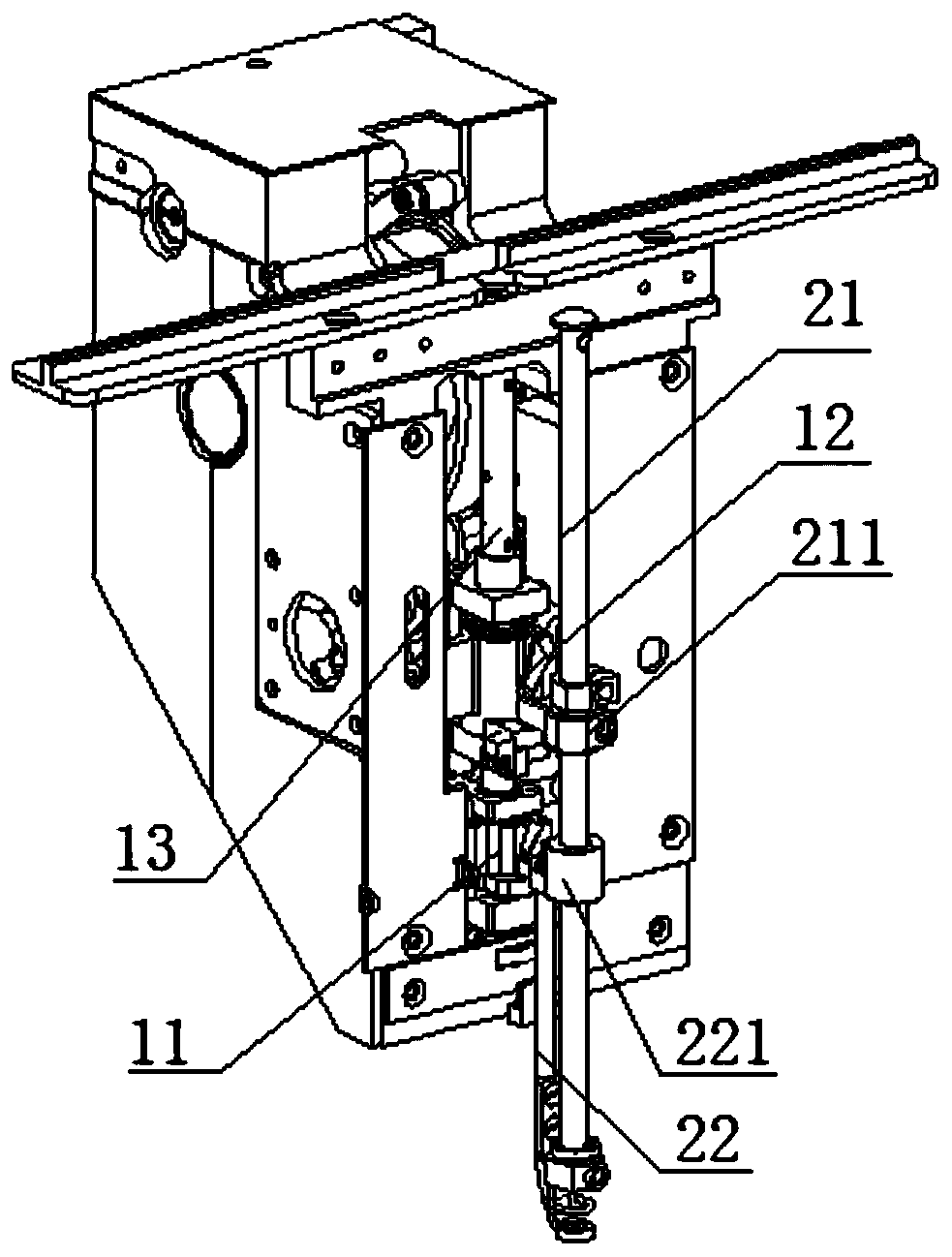
[0030] Such as Figure 2 to Figure 4 As shown, a presser foot driving assembly with stable driving includes a presser foot 22 and a presser foot driver 11, the presser foot 22 has a sliding sleeve 221 slidably installed on the needle bar, and the presser foot driver 11 includes a driving member 112 The driving member 112 is movably engaged with the sliding sleeve 221 and in the fitted state, the driving member 112 drives the sliding sleeve 221 to move up and down synchronously, thereby avoiding impact, reducing noise and improving embroidery quality.

[0031] Wherein, the needle bar 21 is installed on the needle bar frame 2, the needle bar frame 2 has an upper beam and a lower beam, the needle bar 21 moves through the upper beam and the lower beam, and the needle bar 21 is below the upper beam A needle bar driving sleeve 211 is connected, and the needle bar 21 is covered with a presser foot spring 223 that springs downward to press the presser foot between the needle bar drivi...


PUM


Abstract

The invention discloses a presser foot driving assembly with stable driving and an embroidery machine. The presser foot driving assembly comprises a presser foot and a presser foot driver, wherein thepresser foot is provided with a sliding sleeve which is slidably mounted on a needle rod; the presser foot driver comprises a driving piece; the driving piece is movably connected with the sliding sleeve in an embedded mode; and the driving piece drives the sliding sleeve to synchronously move up and down in an embedded state. According to the technical scheme adopted by the invention, in a high-speed embroidering process, the driving piece and the sliding sleeve are movably connected in an embedded mode, and the driving piece drives the sliding sleeve to synchronously move up and down in anembedded state, so that impact is avoided, noises can be reduced, and embroidering quality is improved.

Description

technical field [0001] The invention relates to the technical field of embroidery machines. Background technique [0002] The currently used embroidery machine presser foot driving structure can refer to figure 1 As shown, it includes a presser foot 22 and a presser foot driver 11. The presser foot 22 has a sliding sleeve 221 slidably installed on the needle bar 22. The needle bar 22 is connected with a needle bar driving sleeve 211. The needle bar driver 12 and the presser foot driver 11 slide Installed on the fixed shaft 13, a presser foot spring 223 is provided between the needle bar driving sleeve 211 and the sliding sleeve 221, the presser foot driver 11 includes a driving part, and the driving part has a protruding part 110, and the protruding part is located below the sliding sleeve 221, so that When the needle bar driver 12 drives the needle bar driving sleeve 211 to drive the needle bar 21 to move down, the presser foot 22 also moves down, and at the same time the ...

Claims


Application Information

Patent Timeline
Patent Type & Authority Applications(China)
IPC IPC(8): D05C9/20
CPCD05C9/20
Inventor 王海江田桂郁季海彬
Owner ZHEJIANG XINSHENG SEWING EQUIP
Why Eureka
Try Eureka