Horizontal side-arranged tensioning device for motor rotor conducting bars

A technology for tensioning devices and motor rotors, applied in electromechanical devices, manufacturing squirrel cage rotors, manufacturing motor generators, etc., can solve problems such as uncontrollable, labor-intensive, and uneven shape variables of guide bars

Inactive Publication Date: 2019-11-05
CSR ZHUZHOU ELECTRIC CO LTD
View PDF4 Cites 1 Cited by
  • Summary
  • Abstract
  • Description
  • Claims
  • Application Information

AI Technical Summary

Problems solved by technology

However, manual pneumatic punches are used for impact tensioning, the labor intensity is too large, and the tensioning depth of the guide bars is unstable and the quality is uneven
However, through the jogging impact tensioning method of the equipment, when the narrow notch guide bar is tightened, it is easy to cause the punch to crack, which has hidden dangers to personal and product safety, and when jogging the guide bar, it is easy to cause the rotor to follow Axial runout or radial runout due to impact force, resulting in uneven and uncontrollable deformation of the guide bar, easy to form a wave-like deformation layer on the surface of the guide bar, and uneven tension of the guide bar
[0006] Therefore, how to improve the tensioning efficiency of the motor rotor guide bars, prevent the rotor from running out in the axial or radial direction, ensure that the tension degree of each guide bar is uniform and the tension deformation is uniform and continuous, and eliminate the tension caused by tension during the tensioning operation. The potential safety hazard brought by the punch is a technical problem faced by those skilled in the art

Method used


Image

  • Horizontal side-arranged tensioning device for motor rotor conducting bars
  • Horizontal side-arranged tensioning device for motor rotor conducting bars
  • Horizontal side-arranged tensioning device for motor rotor conducting bars

Examples


Embodiment Construction

[0030] The following will clearly and completely describe the technical solutions in the embodiments of the present invention with reference to the accompanying drawings in the embodiments of the present invention. Obviously, the described embodiments are only some, not all, embodiments of the present invention. Based on the embodiments of the present invention, all other embodiments obtained by persons of ordinary skill in the art without making creative efforts belong to the protection scope of the present invention.

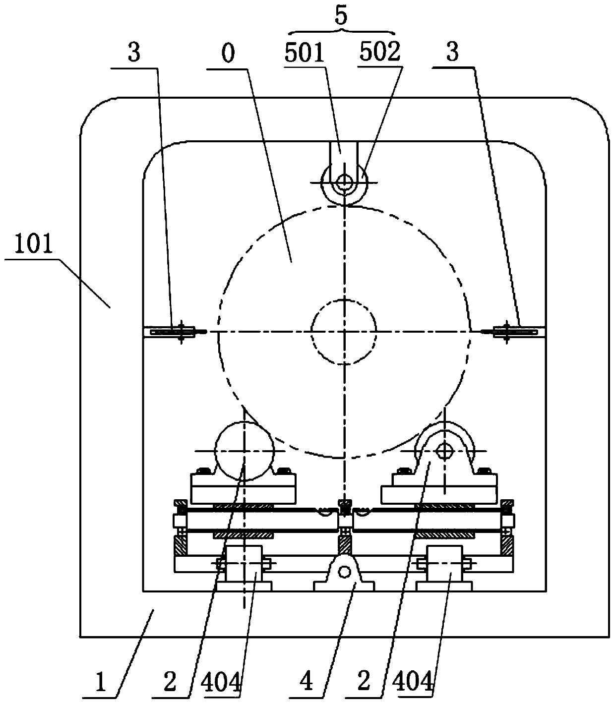
[0031] Please refer to figure 1 , figure 1 It is a schematic diagram of the overall structure of a specific embodiment provided by the present invention.

[0032]In a specific embodiment provided by the present invention, the motor rotor guide bar horizontal overhead tensioning device mainly includes a fuselage base 1, a support rotation mechanism 2, an axial movement mechanism 4, a rolling mechanism 3 and an auxiliary compression mechanism. Agency 5.

[00...


PUM


Abstract

The invention discloses a horizontal side-arranged tensioning device for motor rotor conducting bars, which comprises a machine body base, a supporting and rotating mechanism, axial movement mechanisms, rolling mechanisms and an auxiliary pressing mechanism, wherein the supporting and rotating mechanisms are arranged at two sides of the surface of the machine body base and used for horizontally supporting and circumferentially rotating a rotor workpiece, the axial movement mechanism is used for driving the supporting and rotating mechanisms to drive the rotor workpiece to move in the axial direction in a reciprocating mode, the rolling mechanisms are erected on the machine body base, positioned at two radial sides of the rotor workpiece and used for being tightly abutted against each conducting bar on the rotor workpiece so as to enable the conducting bars to be tensioned in iron core grooves through reciprocating rolling, and the auxiliary pressing mechanism is erected on the machinebody base and used for pressing the surface of the rotor workpiece so as to prevent the rotor workpiece from generating radial or axial runout in the reciprocating movement process. The device disclosed by the invention can improve the tensioning efficiency of the motor rotor conducting bars, prevent the rotor from generating axial or radial runout, ensure the uniform and consistent tensioning degree and uniform and continuous tensioning deformation of each conducting bar and eliminate the potential safety hazards caused by a tensioning punch in the tensioning operation process.

Description

technical field [0001] The invention relates to the technical field of motors, in particular to a horizontal side tensioning device for a motor rotor guide bar. Background technique [0002] With the development of China's machinery industry, more and more machinery and equipment have been widely used. [0003] The occasions involving mechanical rotation often need to be realized by means of electric motors. Three-phase asynchronous motors are a type of induction motors, which are powered by simultaneous access to 380V three-phase AC current. The squirrel-cage motor is a kind of three-phase asynchronous motor. The squirrel-cage rotor is the rotating part of the squirrel-cage motor. Generally, copper or aluminum rotor coils are cast in the cage-shaped slots on the rotor core. [0004] The copper guide bar of the squirrel cage rotor of the AC motor needs to be tightened and fixed in the rotor core slot to prevent the axial displacement of the copper guide bar during the manuf...

Claims


Application Information

Patent Timeline
Patent Type & Authority Applications(China)
IPC IPC(8): H02K15/00
CPCH02K15/0012H02K15/0031H02K15/005
Inventor 马建成郑宇华袁双玲
Owner CSR ZHUZHOU ELECTRIC CO LTD
Why Eureka
Try Eureka