
An automated power transmission device

A technology of power transmission equipment and bottom plate, applied in the field of power transmission, can solve the problems of land burn, freezing of the connection position of the ground electrode and connecting wire, inability to conduct high-voltage leakage, etc., to achieve the effect of stable conduction of the earth and easy maintenance.

Active Publication Date: 2020-10-30
泉州市早稻梦想文化发展有限公司
View PDF28 Cites 0 Cited by
  • Summary
  • Abstract
  • Description
  • Claims
  • Application Information

AI Technical Summary

Problems solved by technology

[0002] Power transmission equipment refers to the alternating current after the electric energy generated by the generator is boosted by the transformer for transmission. There are also a lot of equipment used, such as line towers, wires, insulators, line fittings, pull wires, tower foundations, grounding devices, etc., especially It is the grounding device, which is the most universal. The grounding device refers to the general term for the grounding electrode buried in the ground and the connecting wire from the grounding electrode to the equipment. In a cold environment, the connecting wire will be covered with ice. , it will discharge due to insufficient distance to the ground, causing burns to the surrounding land, making it impossible to perform high-voltage discharge. In addition, the permafrost will also freeze the connection position of the ground electrode and the connecting wire, which is not easy to excavate and detect

Method used


Image

  • An automated power transmission device
  • An automated power transmission device
  • An automated power transmission device

Examples


Embodiment

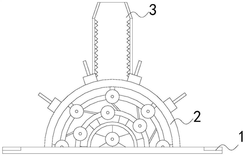
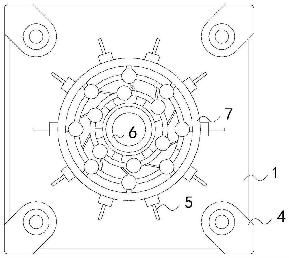
[0028] see Figure 1-Figure 6 , the present invention provides a kind of automatic power transmission equipment, its structure comprises base plate 1, guide ball 2, connecting sleeve 3, fixing screw 4, described base plate 1 is square structure and its four sides corners are installed with fixing screw 4, so The bottom plate 1 is provided with a guide ball 2 in the middle of the surface, and a connecting sleeve 3 is installed in the middle of the top of the guide ball 2. The grounding wire electrically connected to the tower passes through the connecting sleeve 3 and connects with the guide ball 2, and the guide ball 2 2 buried in the soil.

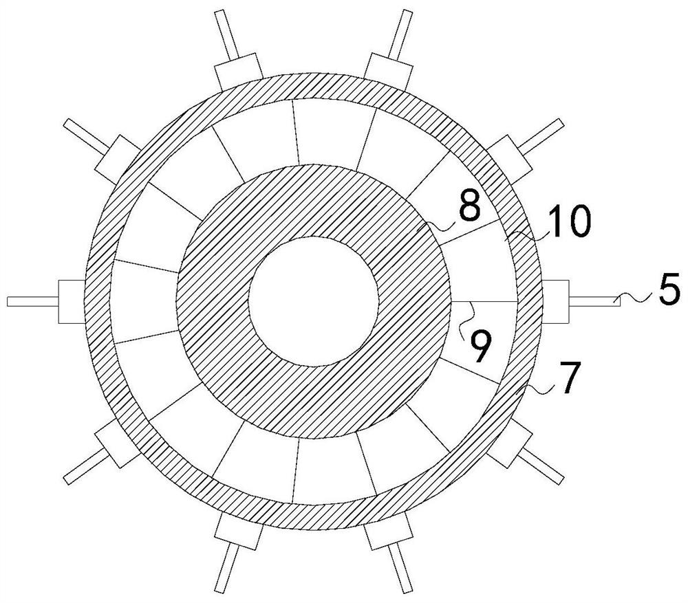
[0029] The guide ball 2 is composed of a plug rod 5, a wiring port 6, a hemispherical shell 7, an installation tin seat 8, a lead wire 9, and a cavity 10. The surface of the hemispherical shell 7 is provided with more than two connecting rods 5, and these connecting rods 5 are distributed evenly and equidistantly. A tin seat 8 is install...


PUM


Abstract

The invention discloses an automatic power transmission device, structurally comprising a bottom plate, a grounding ball, a connecting sleeve and fixing bolts, wherein the bottom plate has a square structure, fixing bolts are movably installed on four corners of the bottom plate, the grounding ball is arranged at the middle of the surface of the bottom plate, the connecting sleeve is installed atthe middle of the top of the grounding ball, an earth lead electrically connected with a tower pole is connected with the grounding ball after passing through the connecting sleeve, the grounding ballis buried in the soil, and the grounding ball is composed of an insertion rod, a wring port, a hemispherical shell, an installation tin seat, a lead and a hollow cavity. According to the automatic power transmission device disclosed by the invention, the contact area between the grounding ball and the soil is increased mainly by the cooperation of the grounding ball, the connecting sleeve and thelike, thereby ensuring full contact between the grounding ball and the soil and protecting the installation tin seat, the electric conduction is not affected even if the soil is frozen, a pressure can also be applied to a cylinder to deform the cylinder, the connection position between the connecting sleeve and the grounding ball is also easy to be loosened, thereby being convenient to maintain,and meanwhile the sharp corner of a V-shaped iron wire and the grounding wire rub against each other to remove the ice covering the surface.

Description

technical field [0001] The invention relates to the field of power transmission, in particular to an automatic power transmission equipment. Background technique [0002] Power transmission equipment refers to the alternating current after the electric energy generated by the generator is boosted by the transformer for transmission. There are also many equipment used, such as line towers, wires, insulators, line fittings, pull wires, tower foundations, grounding devices, etc., especially It is the grounding device, which is the most universal. The grounding device refers to the general term for the grounding electrode buried in the ground and the connecting wire from the grounding electrode to the equipment. In a cold environment, the connecting wire will be covered with ice. , it will discharge due to insufficient distance to the ground, causing burns to the surrounding land, and high-voltage discharge cannot be performed. In addition, the permafrost will freeze the connect...

Claims


Application Information

Patent Timeline
Patent Type & Authority Patents(China)
IPC IPC(8): H01R4/66
CPCH01R4/66
Inventor 黄乾洪王家彬王立飞
Owner 泉州市早稻梦想文化发展有限公司
Learn More