Synchronous driving mechanism of bottom frame of movable rack

A technology of synchronous drive and drive mechanism, applied in mechanical equipment, transmission devices, cabinets for storing books, etc., can solve the problems of heavy weight of the overall hand-crank mechanism, complicated manufacturing process, inconvenient maintenance and repair, etc., and achieve the goal of transmission structure and transmission mode Reasonable, large range of transmission ratio, convenient maintenance

Pending Publication Date: 2019-11-05
江西金虎保险设备集团有限公司
View PDF0 Cites 0 Cited by
  • Summary
  • Abstract
  • Description
  • Claims
  • Application Information

AI Technical Summary

Problems solved by technology

This type of transmission structure has high manufacturing and operating costs, is easy to wear and stretch, and has poor transmission stability. It is prone to additional dynamic load, vibration, impact and noise during operation, and its adaptability to rapid reverse transmission is poor.
The transmission gear meshing structure introduced later has higher manufacturing cost, complicated manufacturing process, inconvenient maintenance, poor adaptability to the operating environment, high operating noise, poor adaptability to speed change, and the overall manual mechanism is heavy and bulky
As for the drive of the chassis, the existing transmission method has a difference in twisting stress and deformation at both ends of the transmission side shaft, which makes the driving force at both ends unbalanced and different in speed, which can easily cause instability such as swinging and vibration when the compact rack is in motion.

Method used


Image

  • Synchronous driving mechanism of bottom frame of movable rack
  • Synchronous driving mechanism of bottom frame of movable rack
  • Synchronous driving mechanism of bottom frame of movable rack

Examples


Embodiment Construction

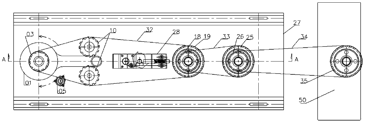
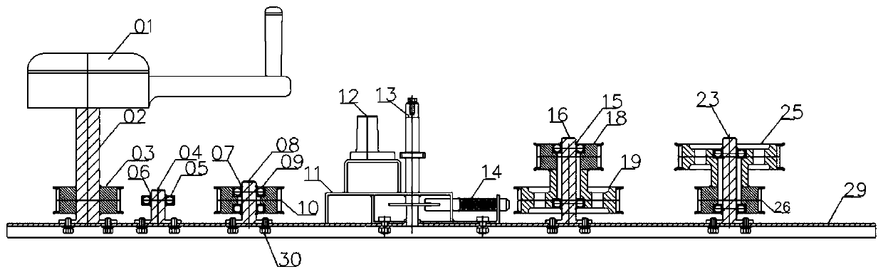
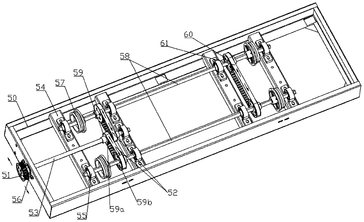
[0009] In order to further understand the technical solution of the present invention, the present invention will be further described by the following embodiments in conjunction with the accompanying drawings. Such as Figure 1-3 The present invention relates to the synchronous transmission chassis of the synchronous drive mechanism of the underframe of the dense rack, the synchronous transmission hand crank mechanism and the like. The synchronous drive manual mechanism includes the main synchronous pulley 03, the transition synchronous pulley, the output synchronous pulley, and the balance tension synchronous pulley, which are arranged on the integrated frame 27 through the corresponding T-axis and the mutual transmission of the corresponding synchronous belt. And locking brake device 28 etc.

[0010] Its transition synchronous pulley includes a transition large synchronous pulley 19 and a transition small synchronous pulley 18 which are arranged on the corresponding transi...


PUM


Abstract

The invention discloses a synchronous driving mechanism of a bottom frame of a movable rack. The synchronous driving mechanism comprises the bottom frame, wherein the bottom frame is a synchronous transmission bottom frame, the synchronous transmission bottom frame comprises a transmission middle shaft, two transmission side shafts which are arranged on two sides of the transmission middle shaft,and iron rollers which are connected to the two ends of the transmission side shafts, the synchronous transmission mechanism is characterized in that the transmission middle shaft is in transmission connection with the transmission side shafts through corresponding transmission synchronous belt wheels and transmission synchronous belts of the transmission synchronous belt wheels, and a coordination balance synchronous belt is further connected between the two transmission side shafts through corresponding coordination balance synchronous belt wheels. The synchronous driving mechanism of the ofthe bottom frame of the movable rack is simple in structure, simple and convenient to use and operate, convenient to maintain, high in transmission efficiency, good in transmission performance, highin running environment adaptability, convenient to maintain, free of lubrication, low in maintenance cost, low in operation noise and stable in operation.

Description

technical field [0001] The invention relates to a synchronous drive mechanism for a compact shelf chassis. Background technique [0002] Most of the existing compact rack drive mechanisms are chain-type transmission structures for the hand-operated mechanism, and chain or gear structure for the driving wheel transmission of the underframe. This type of transmission structure has high manufacturing and operating costs, is easy to wear and stretch, has poor transmission stability, and is prone to additional dynamic load, vibration, impact and noise during operation, and has poor adaptability to rapid reverse transmission. The transmission gear meshing structure introduced later has higher manufacturing cost, complicated manufacturing process, inconvenient maintenance, poor adaptability to the operating environment, high operating noise, poor adaptability to speed change, and the overall manual mechanism is heavy and bulky. As for the drive of the chassis, the existing transmi...

Claims


Application Information

Patent Timeline
Patent Type & Authority Applications(China)
IPC IPC(8): F16H7/02F16H7/08A47B63/00
CPCA47B63/00F16H7/02F16H7/08F16H2007/0842
Inventor 张文渟
Owner 江西金虎保险设备集团有限公司
Why Eureka
Try Eureka