
Container loading and unloading device for port logistics

A loading and unloading device, container technology, applied in the direction of loading/unloading, transportation and packaging, conveyors, etc., can solve the problems of inconvenient storage and achieve the effect of increasing stability

Active Publication Date: 2019-11-05
平湖市超越时空图文设计有限公司
View PDF6 Cites 7 Cited by
  • Summary
  • Abstract
  • Description
  • Claims
  • Application Information

AI Technical Summary

Problems solved by technology

But the device is inconvenient for storing containers that need to be protected from collisions during transport

Method used


Image

  • Container loading and unloading device for port logistics
  • Container loading and unloading device for port logistics
  • Container loading and unloading device for port logistics

Examples


specific Embodiment approach 1

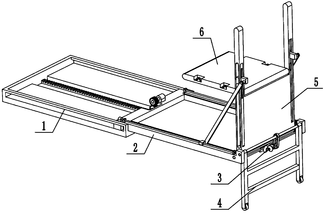
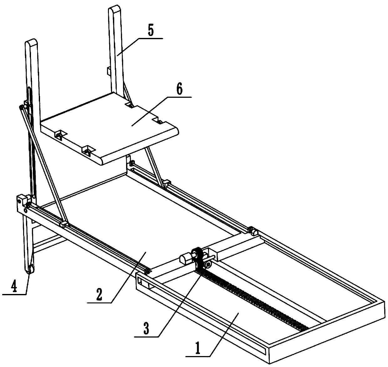
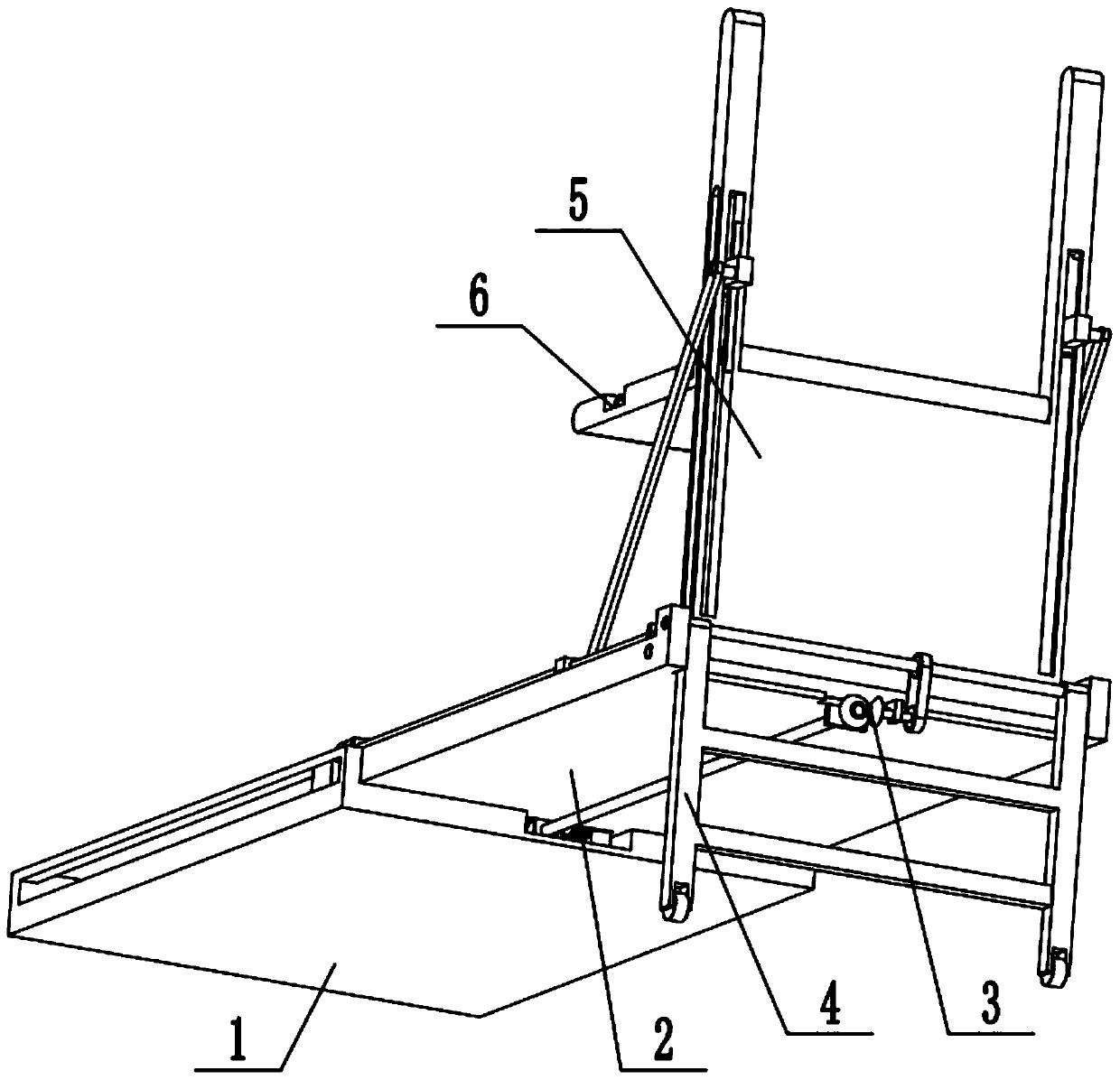
[0032] Combine below Figure 1-15Describe this embodiment, a port logistics container loading and unloading device, including a fixed base 1, a sliding base assembly 2, a power transmission wheel set 3, a support wheel assembly 4, an overturning plate frame mechanism 5 and an overturning storage plate 6, the sliding base The assembly 2 is arranged on the fixed base 1, the sliding base assembly 2 is connected with the fixed base 1 in transmission, the power transmission wheel set 3 is arranged at the lower end of the sliding base assembly 2, the power transmission wheel set 3 is in transmission connection with the sliding base assembly 2, and the supporting wheel assembly 4 is arranged on the right end of the sliding base assembly 2, the supporting wheel assembly 4 is in transmission connection with the power transmission wheel set 3, the flipping frame mechanism 5 is arranged on the sliding base assembly 2, the flipping frame mechanism 5 is in transmission connection with the s...

specific Embodiment approach 2

[0034] Combine below Figure 1-15 To illustrate this embodiment, the fixed base 1 is provided with a U-shaped frame 1-1, a baffle plate 1-2, a rectangular groove 1-3 and a rack I1-4, and two U-shaped racks are symmetrically fixedly connected on the fixed base 1. Frame 1-1, the left end of the fixed base 1 is fixedly connected to the baffle plate 1-2, the middle part of the fixed base 1 is provided with a rectangular slot 1-3, the rack I 1-4 is fixedly connected to the bottom surface of the rectangular slot 1-3, and the sliding base Component 2 is in transmission connection with rack I1-4.

specific Embodiment approach 3

[0036] Combine below Figure 1-15 To illustrate this embodiment, the sliding base assembly 2 includes a sliding plate 2-1, a bump 2-2, a gear placement groove 2-3, a motor I 2-4, a driving gear 2-5, a driven gear 2-6, Worm screw 2-7, receiving groove 2-8, horizontal slide groove 2-9, motor II 2-10, lead screw 2-11, lead screw seat 2-12, guide rod 2-13 and guide rod frame 2-14; slide The left side of the plate 2-1 is symmetrically fixedly connected to two protrusions 2-2, the sliding plate 2-1 is slidingly fitted and connected to the upper end surface of the fixed base 1, and the two protrusions 2-2 are respectively slidingly fitted and connected to two U-shaped Inside the frame 1-1, the left end of the sliding plate 2-1 is provided with a gear placement groove 2-3, the motor I2-4 is fixedly connected to the sliding plate 2-1 through the motor frame, and the output shaft of the motor I2-4 is fixedly connected to the driving gear 2-5, the driving gear 2-5 is meshed with the dri...


PUM


Abstract

The invention discloses a container loading and unloading device for port logistics, and relates to the technical field of container loading and unloading equipment. The container loading and unloading device comprises a fixed base, a sliding base component, a power transmission wheel set, a supporting wheel component, a turnover plate frame mechanism and a turnover storage plate. The container loading and unloading device has the beneficial technical effect that as the turnover plate frame mechanism is arranged, the turnover storage plate is driven to unfold when the turnover plate frame mechanism is unfolded, and a container needing to avoid collision can be placed on the turnover storage plate for separate storage and fixation in the transportation process, and thus the practicality ishigh. The sliding base component is arranged on the fixed base and is in transmission connection with the fixed base, and the power transmission wheel set is arranged at the lower end of the sliding base component and is in transmission connection with the sliding base component. The supporting wheel component is arranged at the right end of the sliding base component and is in transmission connection with the power transmission wheel set, and the turnover plate frame mechanism is arranged on the sliding base component and is in transmission connection with the sliding base component.

Description

technical field [0001] The invention relates to the technical field of container handling equipment, in particular to a port logistics container handling device. Background technique [0002] The existing patent number is CN201820290140.0 for a container loading and unloading auxiliary equipment. This utility model discloses a container loading and unloading auxiliary equipment, which includes a container body and a container loading and unloading platform. The inner bottom side of the container body is fixedly connected with a hydraulic telescopic slide rail , the upper surface of the container loading and unloading platform is fixedly connected with a fixed slide rail, the container loading and unloading platform is connected with the container body, the side of the container loading and unloading platform close to the container body is fixedly installed with a driving gear, and the fixed slide rail The upper frame is connected with a loading board, and guide plates are fi...

Claims


Application Information

Patent Timeline
IPC IPC(8): B65G67/02B65G69/22
CPCB65G67/02B65G69/22B65G2201/0258
Inventor 陈鹏
Owner 平湖市超越时空图文设计有限公司
Learn More