Structure which meets integral abutment pile-soil interaction boundary condition

An integral abutment and boundary condition technology, applied in foundation structure engineering, foundation structure test, construction, etc., can solve problems such as torsion, and achieve the effects of reducing torsion, simple structure and convenient construction

Pending Publication Date: 2019-11-01
FUZHOU UNIV
View PDF0 Cites 2 Cited by
  • Summary
  • Abstract
  • Description
  • Claims
  • Application Information

AI Technical Summary

Problems solved by technology

[0005] This structure largely solves the torsion phenomenon of the traditional H-shaped steel pile during the test, that is, after adopting this method, it will effectively reduce the torsion, deformation and inaccurate test results of the pile, and improve the Component utilization and test accuracy

Method used


Image

  • Structure which meets integral abutment pile-soil interaction boundary condition
  • Structure which meets integral abutment pile-soil interaction boundary condition

Examples


Embodiment Construction

[0022] The present invention will be further described below in conjunction with the accompanying drawings and specific embodiments.

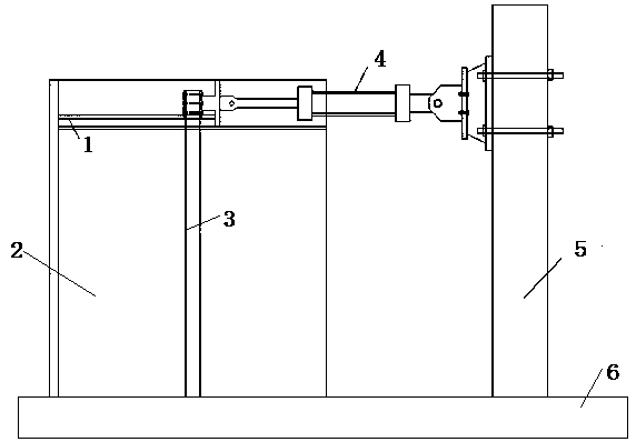
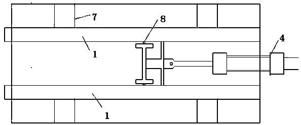
[0023] Such as Figure 1-2 As shown, a structure that satisfies the boundary conditions of the pile-soil interaction of the integral abutment includes a soil box, an MTS loader, and H-shaped steel piles and H-shaped steel beams. The soil box is fixed on the reaction floor, A reaction wall is set beside the soil box on the reaction floor, the MTS loader is placed horizontally, its fixed end is installed on the reaction wall, and the moving end is connected to the H-shaped steel pile. Two H-shaped steel beams welded to the soil box are symmetrically placed horizontally. The H-shaped steel piles are vertically placed in the soil box. Pulleys are installed on the wing plates on both sides of the upper end of the H-shaped steel piles. The wings at the upper and lower ends of the two H-shaped steel beams The inner side of the edge is used as the mot...


PUM


Abstract

The invention relates to a structure which meets the integral abutment pile-soil interaction boundary condition. The structure comprises a soil box and an MTS loader, and further comprises an H-shapedsteel pile and H-shaped steel beams; the soil box is fixed on a reaction floor; a reaction wall is arranged on the part, beside the soil box, on the reaction floor; the MTS loader is transversely arranged; the fixed end of the MTS loader is mounted on the reaction wall; the moving end of the MTS loader is connected with the H-shaped steel pile; the two H-shaped steel beams welded to the soil boxare symmetrically and transversely arranged on the parts, on the two sides of the H-shaped steel pile, of the upper portion of the soil box; the H-shaped steel pile is vertically arranged in the soilbox; flanges on the two sides of the upper end of the H-shaped steel pile are provided with pulleys; the inner sides of the flanges of the upper ends and the lower ends of the two H-shaped steel beamsare used as moving tracks of the pulleys on the same side of the flanges; the pulleys are in sliding fit with the flanges of the corresponding H-shaped steel beams; and the part, blow the pulleys, inthe soil box is filled with sand. The structure is convenient to construct, torsion of the H-shaped steel piles can be greatly reduced, and the accuracy of test results is significantly improved.

Description

technical field [0001] The invention relates to a construction and assembly method satisfying the pile-soil interaction boundary condition of an integral bridge abutment. Background technique [0002] Compared with the traditional simply supported girder bridge, the monolithic bridge is integrated with the upper structure and the lower structure. Under the action of earthquake or temperature load, the horizontal reciprocating load is mainly borne by the abutment and the pile foundation supporting the abutment. In foreign countries, H-shaped steel piles with better deformation capacity are mostly used in the pile foundation of integral bridges, because H-shaped steel piles have better seismic performance and deformation capacity. What needs to be studied is the interaction between H-shaped steel piles and soil under temperature load and vehicle load. For ordinary tests, the interaction between the H-shaped steel pile and the soil usually results in deformation due to torsion...

Claims


Application Information

Patent Timeline
Patent Type & Authority Applications(China)
IPC IPC(8): E02D33/00
CPCE02D33/00
Inventor 黄福云单玉麟张峰罗小烨何凌峰
Owner FUZHOU UNIV
Why Eureka
Try Eureka